
It is easy to say that a heat exchanger “transfers heat.”
But inside real equipment, heat does not jump magically from one stream to another.
It follows a very specific physical path.
It depends on:
- how fluids enter and leave
- how they flow inside the shell or tubes
- how surfaces are arranged
- how contact is maintained
- how distribution behaves
This article explains how heat exchangers execute heat transfer in actual plant equipment — not from a theoretical standpoint, but from what physically happens inside shell-and-tube units, plate exchangers, air coolers, and similar systems.
We are focusing here on execution at equipment level — the mechanical and hydraulic reality that allows thermal energy to move.
Table of Contents
Heat Transfer in Equipment Is a Layered Process
Inside any exchanger, heat must pass through multiple stages.
Even though the physics may be familiar, the way it happens in real equipment depends heavily on construction and flow design.
In practical terms, heat transfer inside an exchanger occurs through:
- Fluid approaching the surface
- Heat crossing the metal wall
- Heat being carried away by the second fluid
Each of these stages depends on how the equipment is built.
The exchanger’s geometry determines how effectively each step happens.
Stage 1: Fluid Must Reach the Surface
Before heat can move through metal, the fluid must come into effective contact with it.
This sounds obvious.
But in real equipment, how fluid approaches the surface depends on:
- inlet nozzle design
- flow distribution
- baffle arrangement
- channel spacing
If fluid distribution is poor:
- some areas receive strong flow
- others receive weak flow
The result is uneven heat transfer.
So the first execution step is not just temperature difference.
It is proper fluid distribution inside the exchanger.
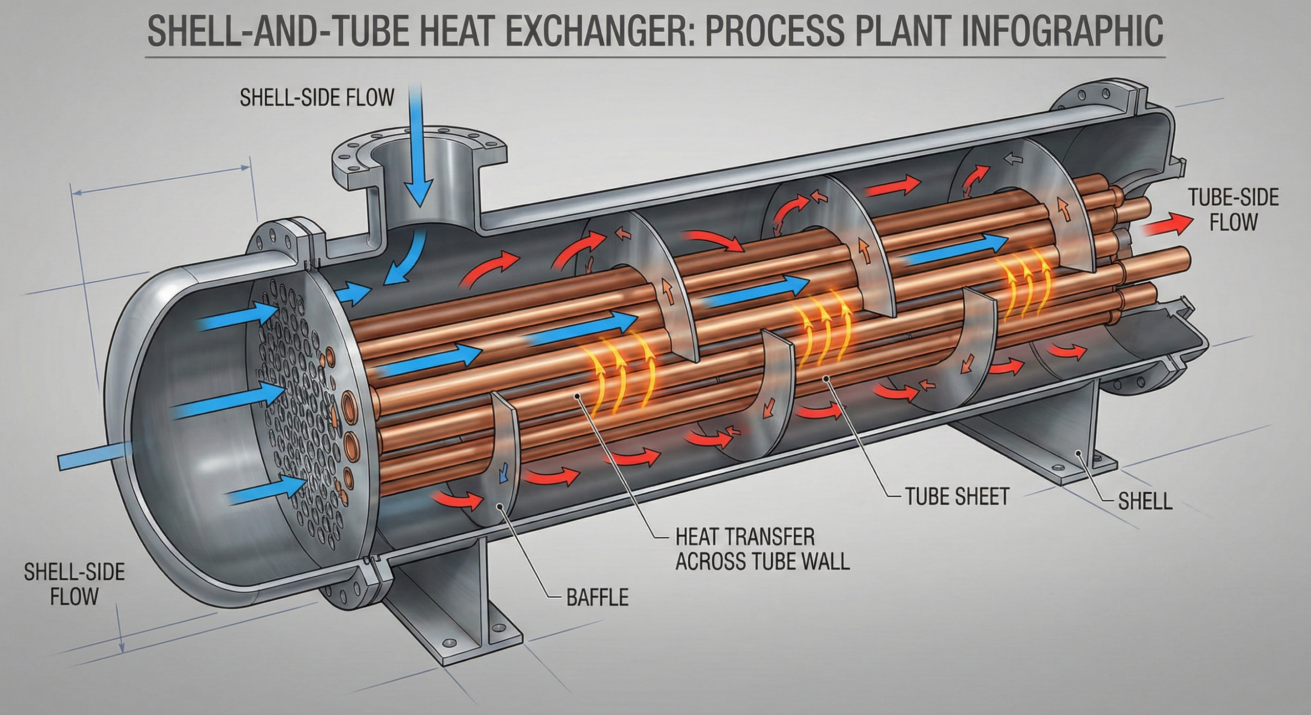
How Shell-and-Tube Units Execute Flow
In shell-and-tube exchangers:
- one fluid flows inside tubes
- the other flows across the tube bundle inside the shell
The tube-side fluid:
- enters through a channel head
- divides into many tubes
- flows along tube length
- exits at the opposite end
The shell-side fluid:
- enters the shell
- is guided by baffles
- flows across tubes in a zigzag pattern
- exits at the outlet nozzle
The baffles are critical.
They force cross-flow across tubes rather than straight-line flow.
Without baffles:
- shell-side fluid would bypass most surfaces
- heat transfer would be weak
So execution depends heavily on internal guiding structures.
Stage 2: Heat Must Cross the Metal Wall
Once fluid contacts the tube surface, heat moves through the metal wall.
This wall:
- separates the two fluids
- prevents mixing
- ensures pressure containment
Heat transfer across this wall depends on:
- material
- thickness
- surface condition
In clean condition, this step is efficient.
If scale or deposits form:
- resistance increases
- heat flow reduces
So while the metal wall is thin, its condition determines how effectively heat moves from one side to the other.
Stage 3: Heat Must Be Carried Away
After heat crosses the wall, the second fluid must carry it away.
If this fluid:
- flows strongly
- mixes well
heat moves away quickly.
If it moves slowly:
- heat accumulates near the surface
- temperature gradient reduces
- transfer weakens
So both sides must execute properly.
Heat transfer fails if either side is poorly distributed.
Plate Heat Exchangers Execute Differently
In plate exchangers:
- thin corrugated plates create narrow channels
- fluids flow in alternating passages
The corrugation pattern creates turbulence even at low flow rates.
This:
- improves surface contact
- enhances mixing
- increases effective transfer area
Execution here relies less on baffles and more on plate geometry.
Because channels are narrow:
- distribution is usually more uniform
- but fouling risk may be higher in dirty services
So execution depends on plate design.
Air Coolers Execute Through Surface Area Multiplication
In air coolers:
- process fluid flows inside tubes
- air flows across finned tubes
Since air has weaker heat carrying capacity:
- fins increase effective surface area
Heat execution here depends on:
- fin contact quality
- air velocity
- distribution across tube banks
If fans do not distribute air evenly:
- some areas overcool
- others underperform
So mechanical airflow design controls execution.
Flow Arrangement Affects Execution
Heat exchangers may use:
- parallel flow
- counterflow
- crossflow
This arrangement affects how temperature difference behaves along the length.
In counterflow:
- temperature difference is maintained more evenly
- transfer remains strong throughout
In parallel flow:
- temperature difference drops quickly
- performance may be less efficient
So execution depends on flow orientation.
The exchanger is designed around this choice.
Internal Passes Shape Performance
Many exchangers use multiple passes.
For example:
- two-pass tube side
- multi-pass shell side
Passes increase velocity.
Higher velocity:
- improves contact
- enhances mixing
- strengthens transfer
But it also increases pressure drop.
So execution involves balancing flow strength and hydraulic resistance.
Surface Condition Defines Real Execution
Even well-designed exchangers lose effectiveness when:
- fouling builds
- corrosion roughens surfaces
- deposits accumulate
Heat must pass through whatever layer sits between fluid and metal.
So real execution depends not only on geometry but on cleanliness.
A clean exchanger and a fouled exchanger execute heat transfer very differently, even though they look identical externally.
Distribution Matters More Than Area
Two exchangers with identical surface area can perform differently if:
- one has good distribution
- the other has channeling or bypass
In shell-and-tube units:
- damaged baffles cause shell-side bypass
- flow avoids parts of the bundle
In plate units:
- gasket issues may disturb channel flow
So execution quality depends on internal flow integrity.
Startup Behavior Reveals Execution Path
During startup:
- metal warms first
- temperature gradient develops
- flow stabilizes
If heating is uneven:
- some tubes expand faster
- stress develops
So how heat executes across surfaces affects mechanical behavior as well.
Execution is not just thermal — it has structural impact.
Why Some Exchangers “Look Fine” But Underperform
Externally, an exchanger may appear normal.
But internally:
- partial blockage
- uneven fouling
- tube plugging
- fin damage
can disrupt execution.
Heat transfer depends on internal condition.
Not external appearance.
Operator Perspective
Operators see execution indirectly through:
- inlet/outlet temperatures
- approach temperature changes
- pressure drop increase
When temperature targets drift:
- execution is being restricted somewhere inside.
Understanding how heat moves physically helps diagnose root causes.
Owner Perspective
From a long-term view, execution quality affects:
- energy cost
- maintenance frequency
- reliability
- capital replacement timing
Better internal design and maintenance improve long-term energy performance.
Why “Execution” Is the Right Word
Heat exchangers do not merely exist.
They execute a controlled movement of thermal energy through:
- engineered flow paths
- guided surfaces
- mechanical separation
The geometry and flow design determine how effectively that execution occurs.
Final Perspective
Inside every heat exchanger, heat follows a structured path:
Fluid approaches the surface.
Heat crosses metal.
Another fluid carries it away.
How well this happens depends on:
- internal flow design
- geometry
- surface condition
- distribution quality
Real equipment performance is defined not just by temperature difference, but by how effectively the exchanger executes the physical movement of heat.
And that execution depends entirely on how the equipment is built and maintained.

A practicing chemical engineer with 17+ years of experience in process design, project execution, commissioning, and plant operations. Focused on practical engineering judgment beyond textbook explanations.