
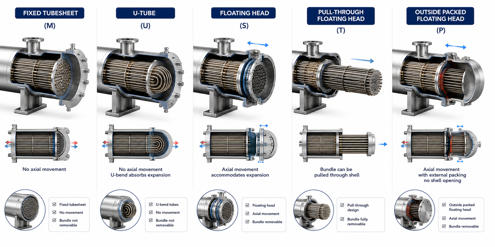
The Rear Head Determines How the Tube Bundle Expands, Is Cleaned, and Is Maintained
When engineers first encounter a TEMA designation such as:
- BEM
- AES
- BEU
- AET
they usually focus on the first two letters.
However, the third letter is equally important.
It identifies the rear head—the section at the opposite end of the exchanger that determines how the tube bundle is supported, how thermal expansion is accommodated, and how maintenance is performed.
Unlike the front head, which mainly controls tube-side flow entry and exit, the rear head influences the exchanger’s long-term mechanical behavior.
Selecting the wrong rear head can lead to:
- excessive thermal stress
- difficult maintenance
- unnecessary capital cost
- limited cleaning capability
This article explains the most common TEMA rear head types, their construction, applications, advantages, and the engineering logic behind selecting each one.
Table of Contents
What Is the Rear Head?
The Rear Head Is More Than the End Cover
The rear head is located at the opposite end of the exchanger from the front head.
Its functions include:
- supporting the tube bundle
- allowing tube-side flow reversal in multi-pass exchangers
- accommodating thermal expansion
- providing maintenance access where applicable
Although it occupies only one end of the exchanger, it largely determines the exchanger’s mechanical flexibility.
Why TEMA Defines Multiple Rear Head Types
Different Services Require Different Mechanical Solutions
Not every exchanger experiences the same operating conditions.
Some operate with:
- small temperature differences
- clean fluids
- minimal thermal expansion
Others experience:
- large shell-to-tube temperature differences
- severe fouling
- frequent cleaning
- repeated thermal cycling
A single rear head design cannot efficiently serve every application.
TEMA therefore standardizes several rear head arrangements, allowing engineers to select the design that best fits the process conditions.
Fixed Tubesheet (M Type)
The Simplest Rear Head Arrangement
In a fixed tubesheet exchanger, both ends of the tube bundle are permanently attached to the tubesheets.
The tube bundle cannot be removed from the shell.
The shell and tube bundle become one integrated assembly.
Where Fixed Tubesheets Are Used
This arrangement is commonly selected when:
- shell-side fluid is clean
- shell-side mechanical cleaning is unnecessary
- temperature difference between shell and tubes is relatively small
Typical applications include:
- cooling water exchangers
- clean utility services
- general process cooling
Advantages
- Lowest fabrication cost
- Simple construction
- Good mechanical rigidity
- Fewer components
Limitations
Since the tube bundle cannot be removed:
- shell-side cleaning is difficult
- shell-side inspection is limited
Large thermal expansion differences may also create mechanical stress.
Floating Head (S and T Types)
Designed to Handle Thermal Expansion
Floating head exchangers allow one end of the tube bundle to move independently.
As temperatures change:
- tubes expand
- shell expands
The floating head accommodates this movement without creating excessive stress.
Why Floating Heads Are Important
In services with large temperature differences, differential expansion is unavoidable.
Without movement allowance:
- tubes may buckle
- gasket leakage may occur
- mechanical stress increases
Floating heads solve this problem by allowing controlled movement.
Typical Applications
Floating head exchangers are widely used in:
- refinery units
- petrochemical plants
- crude preheat trains
- high-temperature process services
These applications often involve severe thermal cycling.
Advantages
- Excellent thermal expansion accommodation
- Tube bundle removable for cleaning
- Suitable for severe operating conditions
- Good maintenance accessibility
Limitations
The improved flexibility comes with:
- higher fabrication cost
- more components
- more sealing surfaces
Despite these drawbacks, floating heads remain popular in demanding services.
U-Tube Rear Head (U Type)
Expansion Through Tube Flexibility
Instead of allowing one tubesheet to move, U-tube exchangers use bent tubes.
Each tube forms a U-shape.
As temperature changes:
- the tubes flex naturally
- thermal expansion is absorbed by tube bending
This eliminates the need for a floating head assembly.
Why U-Tube Designs Are Popular
U-tube exchangers provide thermal flexibility with fewer mechanical components.
They are particularly attractive when:
- shell-side cleaning is required
- tube-side fouling is relatively low
- thermal expansion is significant
Typical Applications
Common services include:
- high-temperature utilities
- steam heaters
- condensers
- refinery process exchangers
Advantages
- Good thermal expansion capability
- Lower cost than floating head designs
- Removable tube bundle
- Fewer gasket joints
Limitations
Because tubes are bent:
- individual tube replacement is more difficult
- mechanical tube cleaning is limited near the bend
- tube layout flexibility is reduced
These factors must be considered during selection.
Pull-Through Floating Head (T Type)
Simplifying Maintenance
The pull-through floating head is designed so the complete tube bundle can be removed without dismantling the floating head separately.
This simplifies maintenance during plant shutdowns.
Typical Applications
Pull-through designs are often selected for:
- heavily fouling services
- frequent maintenance requirements
- refinery process units
Advantages
- Easy tube bundle removal
- Excellent maintenance accessibility
- Suitable for severe fouling
Limitations
- Higher equipment cost
- Larger rear head assembly
- Increased exchanger length
The maintenance benefits often justify these disadvantages.
Outside Packed Floating Head (P Type)
A Less Common Arrangement
The outside packed floating head uses packing glands to seal the moving tubesheet.
It allows thermal expansion while reducing some construction complexity.
Typical Applications
Historically, this arrangement was used in:
- moderate-pressure services
- thermal expansion applications
Its use has declined because modern floating head designs generally provide better long-term sealing performance.
Advantages
- Accommodates expansion
- Simpler than some floating head arrangements
Limitations
- Packing maintenance required
- Potential leakage risk
- Less common in modern process plants
Comparing the Common Rear Head Types
| Rear Head Type | Thermal Expansion | Tube Bundle Removal | Mechanical Cleaning | Relative Cost |
|---|---|---|---|---|
| Fixed Tubesheet (M) | Limited | No | Tube side only | Low |
| Floating Head (S/T) | Excellent | Yes | Excellent | High |
| U-Tube (U) | Excellent | Yes | Moderate | Medium |
| Outside Packed (P) | Good | Yes | Good | Medium |
Each arrangement solves a different mechanical challenge.
How Engineers Select the Rear Head
Step 1 – Evaluate Thermal Expansion
If shell and tube temperatures differ significantly:
- floating head or U-tube designs become attractive.
If temperature difference is modest:
- fixed tubesheet construction may be sufficient.
Step 2 – Consider Fouling
If shell-side fouling is expected:
- removable tube bundles become valuable.
If both fluids remain clean:
- fixed tubesheet construction may reduce cost.
Step 3 – Consider Maintenance Philosophy
Plants with frequent turnarounds often prefer exchangers that allow:
- rapid inspection
- bundle removal
- efficient cleaning
Maintenance strategy strongly influences rear head selection.
Step 4 – Evaluate Lifecycle Cost
A more expensive rear head may reduce:
- shutdown duration
- cleaning cost
- maintenance labor
Lifecycle economics often outweigh initial fabrication savings.
Common Misunderstanding About Rear Heads
A common misconception is that the rear head simply closes the exchanger.
In reality, it determines:
- whether the tube bundle can be removed
- how thermal expansion is handled
- how maintenance is performed
- how long the exchanger remains reliable under changing temperatures
Mechanically, it is one of the most important sections of the exchanger.
Why Fixed Tubesheet and U-Tube Designs Are So Common
Although many rear head arrangements exist, two designs dominate industrial applications.
Fixed tubesheet exchangers are preferred for:
- clean services
- lower cost
- simple operation
U-tube exchangers are preferred when:
- thermal expansion is significant
- removable bundles are required
- maintenance flexibility is important
Floating heads are selected when the service demands maximum accessibility despite higher cost.
Operator Perspective
Operators rarely notice the rear head during normal operation.
Its importance becomes evident during:
- shutdowns
- inspections
- exchanger cleaning
- bundle replacement
The ease of maintenance often depends entirely on rear head selection.
Owner Perspective
For plant owners, rear head selection affects:
- fabrication cost
- maintenance duration
- lifecycle reliability
- turnaround planning
- long-term operating cost
A properly selected rear head reduces operational disruptions throughout the exchanger’s service life.
Final Perspective
The rear head is not simply the end of a shell-and-tube heat exchanger.
It determines how the exchanger expands, how it is maintained, and how it survives years of thermal cycling.
Fixed tubesheet designs offer simplicity.
U-tube designs provide economical thermal flexibility.
Floating head designs maximize maintenance accessibility and reliability under severe operating conditions.
Selecting the correct rear head is therefore not a mechanical detail—it is a long-term engineering decision that influences maintenance, reliability, and lifecycle cost throughout the exchanger’s operating life.
Explore the complete series in the Heat Exchanger Engineering Hub.

A practicing chemical engineer with 17+ years of experience in process design, project execution, commissioning, and plant operations. Focused on practical engineering judgment beyond textbook explanations.