
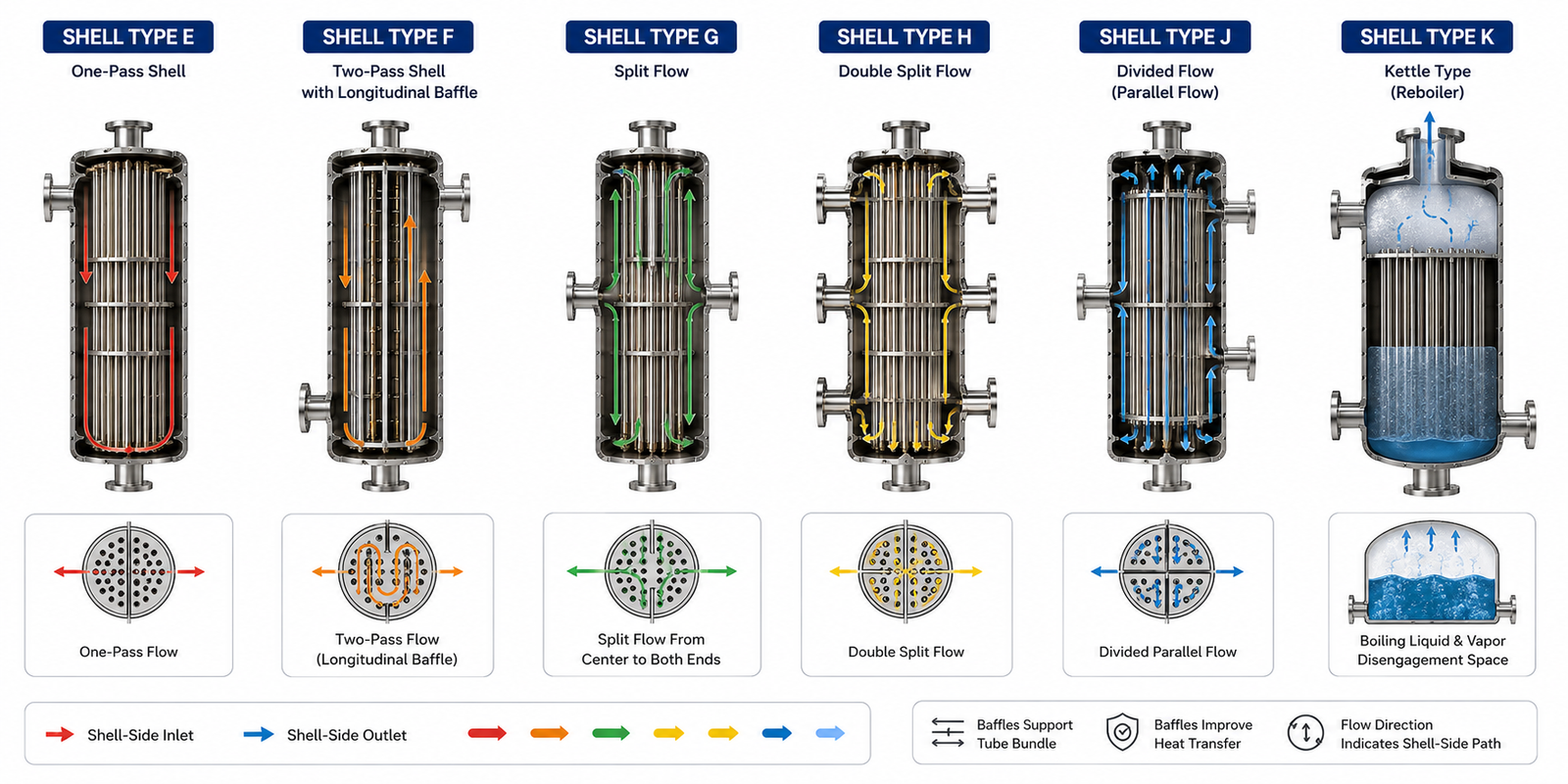
The Shell Type Determines How the Shell-Side Fluid Flows and How Efficiently Heat Is Transferred
When engineers see a TEMA designation such as:
- BEM
- AES
- AET
- BEU
they often recognize that:
- the first letter identifies the front head
- the second letter identifies the shell
- the third letter identifies the rear head
Among these three, the shell type has one of the greatest influences on exchanger performance.
Why?
Because the shell determines:
- how the shell-side fluid moves
- how many times it crosses the tube bundle
- how evenly heat is distributed
- how pressure drop develops
- how suitable the exchanger is for condensation or boiling
Changing the shell type does not change the tubes.
It changes the way the shell-side fluid behaves.
That seemingly small design choice can significantly affect thermal performance, pressure loss, maintenance, and operating cost.
This article explains the most common TEMA shell types—E, F, G, H, J, and K—their construction, applications, and selection logic.
Table of Contents
What Is the Shell in a Shell-and-Tube Heat Exchanger?
The Shell Is More Than an Outer Pressure Vessel
Many beginners think the shell is simply the outer cylinder that surrounds the tubes.
Mechanically, that is true.
Functionally, however, the shell is much more important.
It controls:
- shell-side flow direction
- velocity distribution
- pressure drop
- heat transfer pattern
- fluid residence time
The shell is where engineers influence shell-side thermal performance.
Why TEMA Defines Different Shell Types
One Flow Pattern Cannot Solve Every Process Requirement
Different industrial services require different shell-side behavior.
For example:
- a crude oil cooler behaves differently from a condenser
- a reboiler behaves differently from a feed preheater
- a high-pressure gas exchanger behaves differently from a low-pressure water cooler
Instead of designing a completely new exchanger for every service, TEMA standardizes several shell arrangements.
Each shell type creates a different shell-side flow pattern.
Type E Shell – The Standard One-Pass Shell
The Most Common TEMA Shell
Type E is the default shell arrangement used throughout industry.
It contains:
- one shell-side inlet
- one shell-side outlet
- single-pass shell-side flow
The shell-side fluid enters one end, crosses the tube bundle through baffles, and leaves from the opposite end.
Why Type E Is So Popular
Its simplicity provides:
- straightforward fabrication
- predictable performance
- reasonable pressure drop
- easy mechanical design
It satisfies the majority of industrial heating and cooling duties.
Typical Applications
Type E shells are widely used in:
- process coolers
- feed preheaters
- product coolers
- utility exchangers
- general process services
If there is no special process requirement, engineers usually begin with a Type E shell.
Advantages
- Simple construction
- Lowest fabrication cost
- Well-understood design methods
- Broad operating experience
- Easy maintenance
Limitations
Since shell-side flow occurs only once across the exchanger:
- temperature driving force may not be fully optimized
- very close temperature approaches can be difficult
For many services, however, these limitations are acceptable.
Type F Shell – Two-Pass Shell
Designed for Closer Temperature Approach
The Type F shell introduces a longitudinal baffle inside the shell.
This divides the shell into two flow passages.
The shell-side fluid travels:
- through one half of the shell
- reverses direction
- returns through the second half
Effectively, the shell-side fluid makes two passes.
Why Engineers Choose Type F
This arrangement increases:
- shell-side velocity
- temperature effectiveness
- thermal performance
It is often selected when:
- closer outlet temperatures are required
- heat recovery is important
Typical Applications
Type F shells are commonly used in:
- process-to-process heat recovery
- feed preheating
- energy integration systems
Trade-Offs
Advantages:
- improved thermal effectiveness
- better temperature utilization
Limitations:
- higher pressure drop
- more complex fabrication
- increased shell-side flow resistance
Type G Shell – Split Flow Shell
Flow Moves Toward Both Ends
In a Type G shell, shell-side fluid enters near the center of the exchanger.
The flow then splits into two directions.
Each portion moves toward opposite ends before leaving the shell.
Why Split Flow Helps
This arrangement reduces:
- shell-side pressure drop
- overall flow length
It becomes useful when pressure loss must be minimized.
Typical Applications
Type G shells are selected for:
- large flow rates
- pressure-sensitive services
- moderate heat duties
Trade-Offs
Advantages:
- lower pressure drop
- balanced flow paths
Limitations:
- less common
- more specialized applications
Type H Shell – Double Split Flow Shell
A Variation of Split Flow
Type H expands the split-flow concept further.
Shell-side flow divides into multiple directions before leaving the exchanger.
This significantly reduces flow length.
Why It Is Used
Type H shells are useful when:
- shell-side pressure drop must be extremely low
- flow rates are very large
Typical Applications
Examples include:
- vacuum services
- gas cooling
- large-volume utility systems
Trade-Offs
Advantages:
- very low shell-side pressure loss
- suitable for gas services
Limitations:
- lower shell-side velocity
- reduced heat transfer intensity
- specialized construction
Type J Shell – Divided Flow Shell
Flow Moves Through Parallel Paths
Type J shells divide shell-side flow into parallel paths.
Unlike split-flow arrangements, the emphasis is on reducing hydraulic resistance while maintaining acceptable heat transfer.
Where It Is Used
Type J is commonly selected when:
- shell-side pressure drop is highly restricted
- gas density is low
- pumping or compression cost is significant
Advantages
- reduced pressure drop
- improved hydraulic performance
Limitations
Because velocity decreases:
- shell-side heat transfer coefficient may also decrease
Engineers must balance hydraulic savings against thermal performance.
Type K Shell – Kettle Reboiler Shell
Designed Specifically for Boiling Service
Unlike the previous shell types, Type K has a completely different purpose.
It is used almost exclusively as a kettle reboiler.
The shell contains a large liquid reservoir.
Heat supplied through the tubes causes the shell-side liquid to boil.
The generated vapor leaves through the top of the shell.
Why Type K Is Different
The objective is not simply sensible heating.
It is controlled boiling.
The shell provides:
- liquid inventory
- vapor disengagement space
- stable boiling conditions
Typical Applications
Type K shells are widely used in:
- distillation columns
- fractionation units
- refinery reboilers
- petrochemical separation systems
Advantages
- excellent boiling stability
- good vapor separation
- reliable natural circulation
Limitations
- larger shell diameter
- higher equipment weight
- greater liquid inventory
- higher capital cost
Despite these limitations, Type K remains the preferred design for kettle reboilers.
Comparing the Common TEMA Shell Types
| Shell Type | Main Flow Pattern | Primary Objective | Typical Application |
|---|---|---|---|
| E | One-pass | General heat transfer | Most industrial exchangers |
| F | Two-pass | Better temperature approach | Heat recovery |
| G | Split flow | Lower pressure drop | Large liquid services |
| H | Double split flow | Very low pressure drop | Gas and vacuum services |
| J | Divided flow | Hydraulic efficiency | Pressure-sensitive services |
| K | Kettle | Boiling and vapor generation | Reboilers |
The table highlights an important principle:
Different shell types solve different engineering problems.
How Engineers Select the Shell Type
Step 1 – Evaluate Heat Transfer Requirement
If conventional heating or cooling is required:
Type E is usually the starting point.
Step 2 – Evaluate Pressure Drop
If shell-side pressure drop is limited:
Types G, H, or J may become better choices.
Step 3 – Evaluate Temperature Approach
If close temperature approach is important:
Type F may improve exchanger effectiveness.
Step 4 – Evaluate Phase Change
If shell-side boiling is required:
Type K is normally selected.
Common Misunderstanding About Shell Types
A common misconception is that changing the shell type automatically increases heat transfer.
That is not always true.
Changing the shell affects:
- flow path
- velocity
- pressure drop
- residence time
Sometimes thermal performance improves.
Sometimes hydraulic performance improves.
Sometimes one improves while the other becomes less favorable.
The correct shell type depends on the overall process objective.
Why Type E Dominates Industrial Plants
If you examine exchanger inventories in large process plants, Type E shells usually represent the majority.
This is because they offer:
- balanced performance
- simple fabrication
- predictable maintenance
- broad applicability
Special shell types are selected only when the process requires a specific flow characteristic.
Operator Perspective
Operators rarely identify exchangers by shell type during daily operation.
However, shell configuration influences:
- pressure drop trends
- temperature response
- process stability
- utility consumption
Although invisible from the outside, shell design directly affects operating behavior.
Owner Perspective
From a lifecycle perspective, shell selection influences:
- fabrication cost
- operating cost
- pumping energy
- maintenance complexity
- equipment reliability
Selecting the appropriate shell type reduces unnecessary operating expenses while improving exchanger performance.
Final Perspective
The shell of a shell-and-tube heat exchanger is far more than its outer casing.
It determines how the shell-side fluid moves, how heat is transferred, and how pressure losses develop.
Type E provides versatility.
Type F improves temperature effectiveness.
Types G, H, and J reduce pressure drop.
Type K enables reliable boiling.
Understanding these shell types allows engineers to select exchangers based not only on heat duty, but also on the hydraulic and thermal behavior required by the process.
That is the real engineering purpose behind the second letter of the TEMA classification system.
Explore the complete series in the Heat Exchanger Engineering Hub.

A practicing chemical engineer with 17+ years of experience in process design, project execution, commissioning, and plant operations. Focused on practical engineering judgment beyond textbook explanations.