skip to content

August 28, 2026

processplantinsights.com

processplantinsights.com

  • About
  • Heat Transfer
  • Heat Exchanger

Heat Exchanger Design

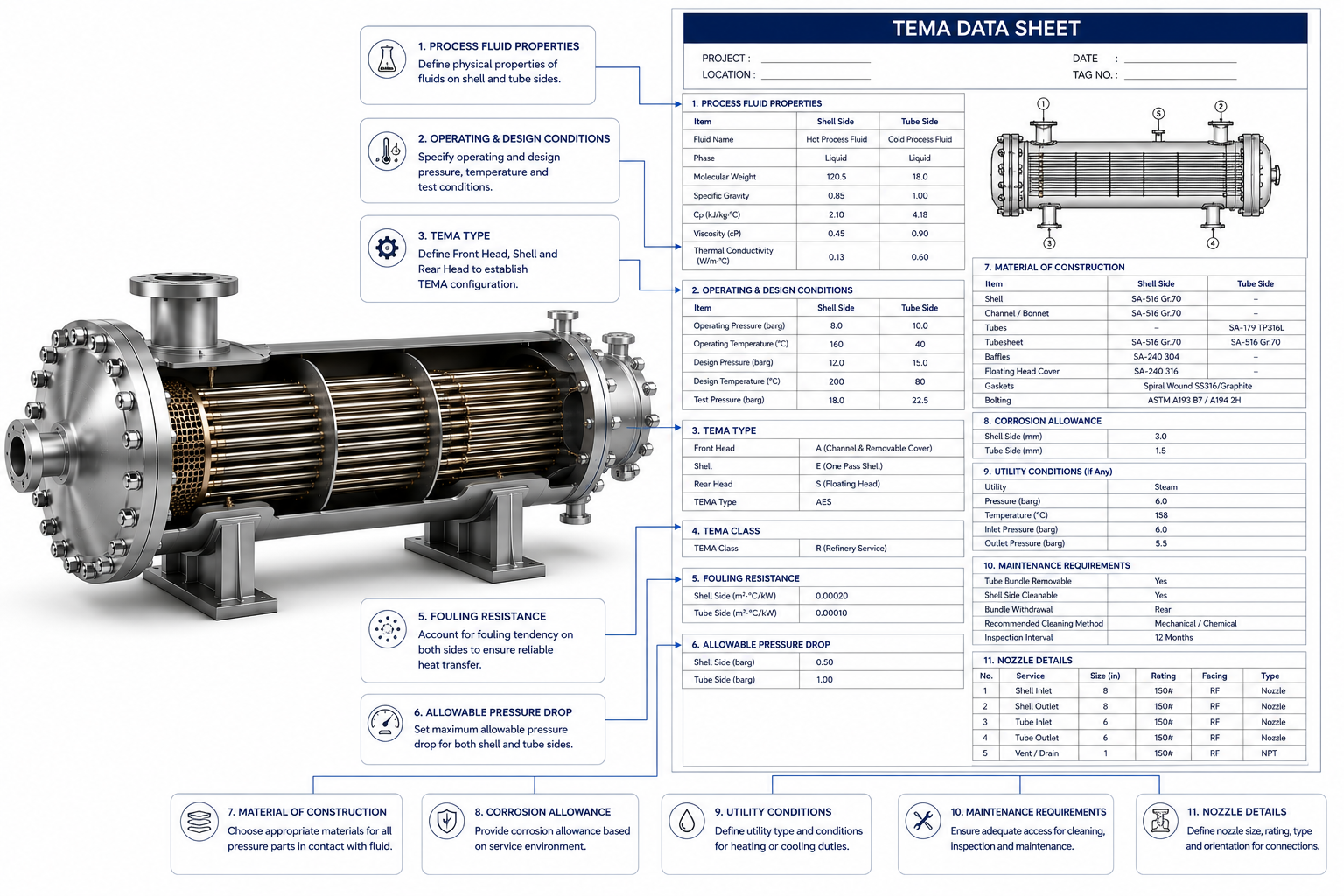
Engineering heat exchanger TEMA data sheet highlighting critical specification items for shell and tube exchangers
PPI August 2, 2026 0

Critical TEMA Data Sheet Items Engineers Often Miss

A Heat Exchanger Is Only as Good as the Information Provided in Its Data Sheet In most engineering companies, the thermal design of a shell-and-tube heat exchanger begins with a…

READ MORE +
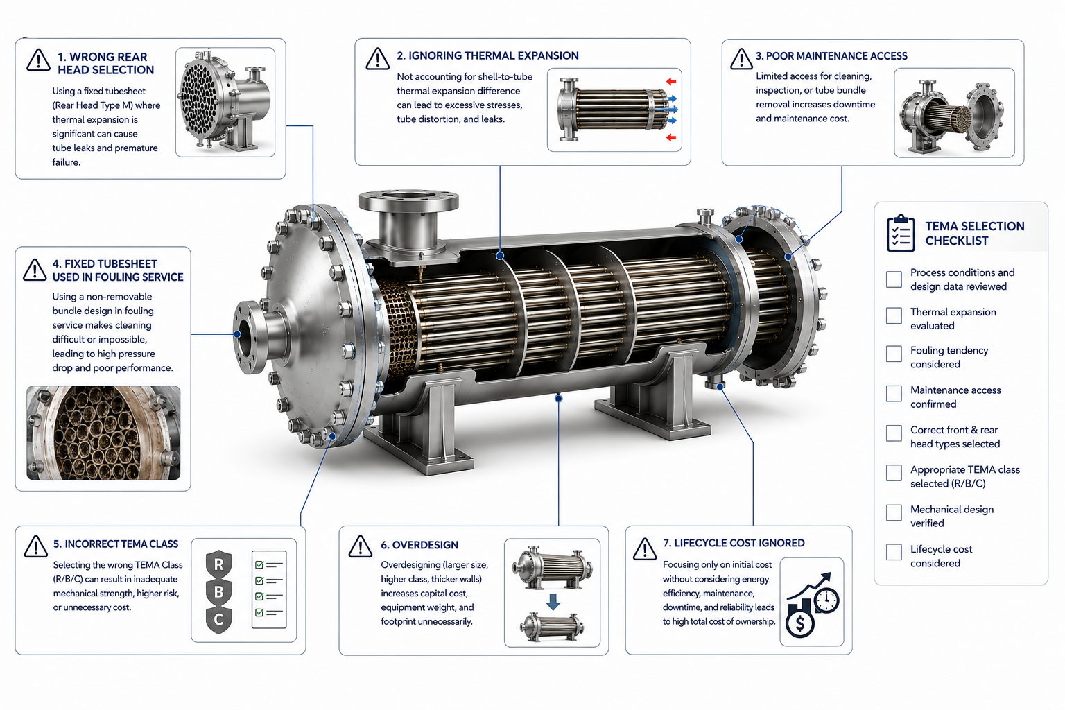
Engineering infographic showing common TEMA selection mistakes for shell-and-tube heat exchangers
PPI July 30, 2026 0

Common TEMA Selection Mistakes Engineers Make

Most Heat Exchanger Problems Start During Selection—Not During Operation When a shell-and-tube heat exchanger underperforms, engineers often blame: Sometimes those are the real causes. But in many industrial plants, the…

READ MORE +
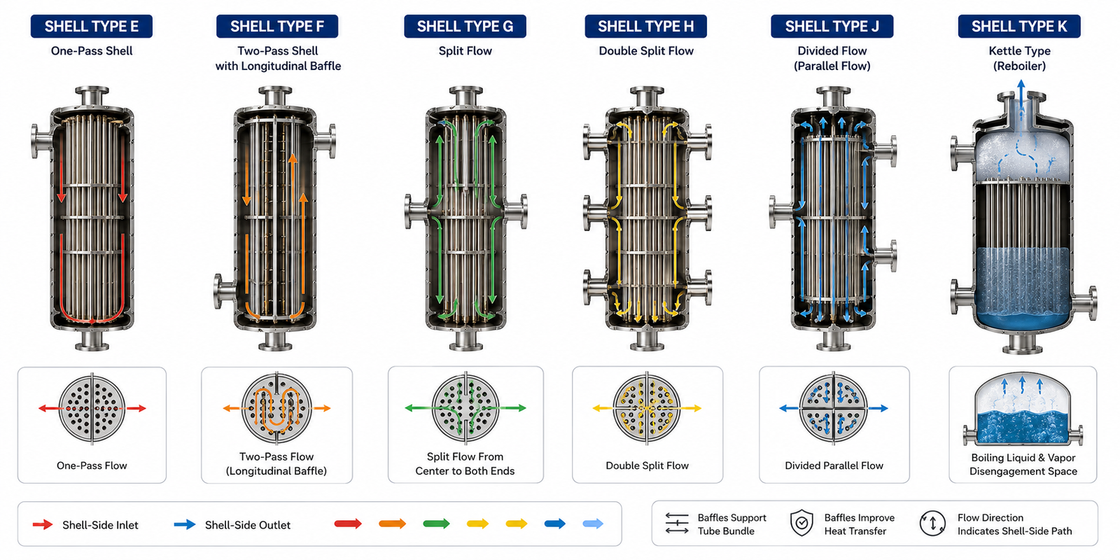
Comparison of TEMA shell types E, F, G, H, J, and K showing different shell-side flow patterns in shell and tube heat exchangers
PPI July 19, 2026 0

TEMA Shell Types (E, F, G, H, J, K) Explained

The Shell Type Determines How the Shell-Side Fluid Flows and How Efficiently Heat Is Transferred When engineers see a TEMA designation such as: they often recognize that: Among these three,…

READ MORE +
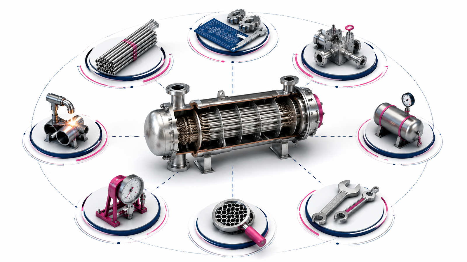
Engineering illustration showing what TEMA standards control in shell and tube heat exchangers including design, fabrication, inspection, and maintenance
PPI July 14, 2026 0

TEMA Standards Explained – What TEMA Controls

More Than a Design Standard—It Defines How Shell & Tube Heat Exchangers Are Built, Inspected, and Maintained. When engineers first encounter a shell-and-tube heat exchanger datasheet, one of the first…

READ MORE +
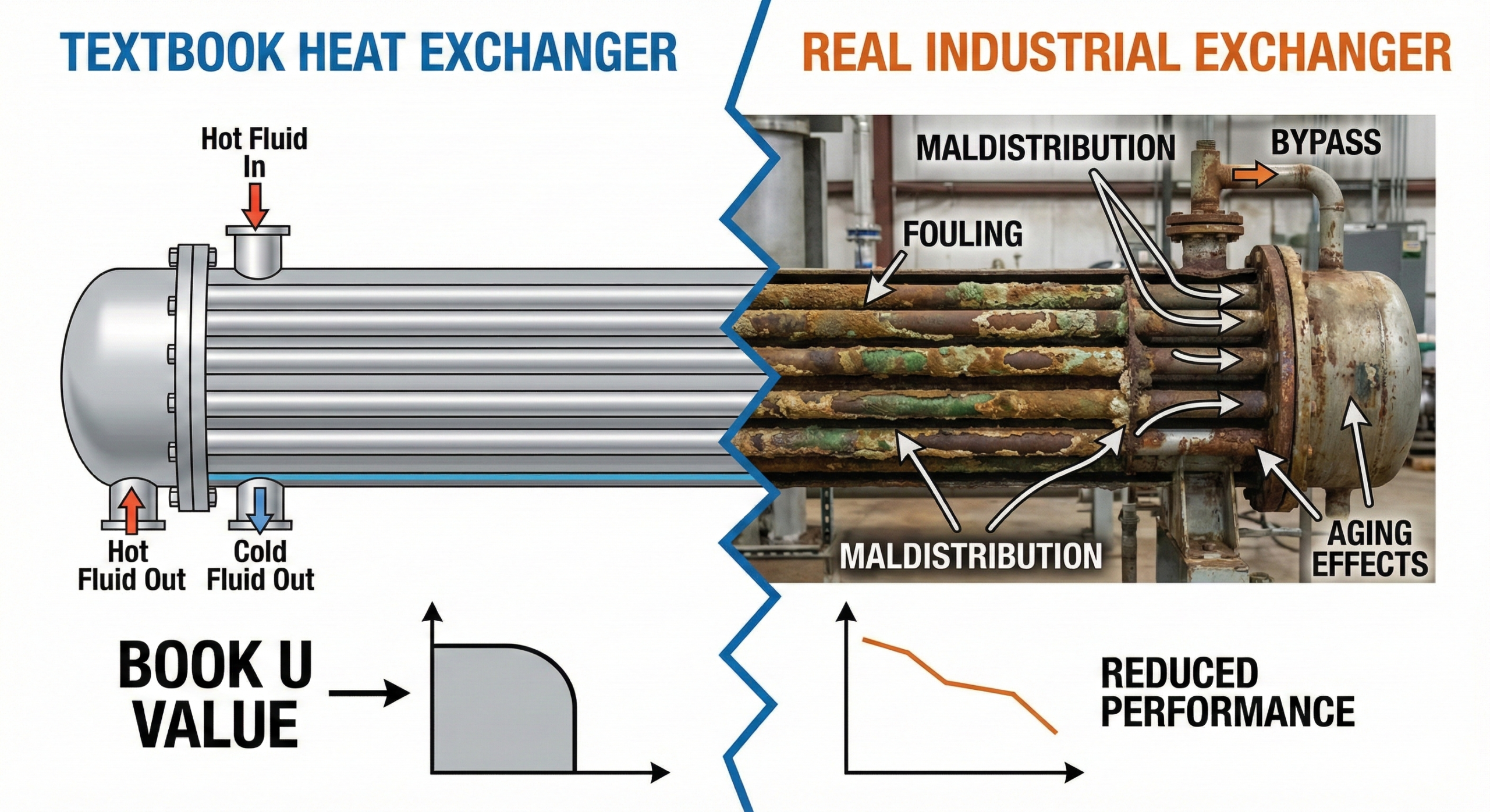
Comparison illustration of textbook U value assumptions versus real heat exchanger performance affected by fouling and aging
PPI March 17, 2026 0

Why U Values from Books Fail in Plants – Because Real Heat Transfer Is Messier Than Any Table Can Capture

Textbooks, handbooks, and design manuals are full of neat tables listing typical U values for different services. These tables are widely used during preliminary design and quick checks. Yet in…

READ MORE +
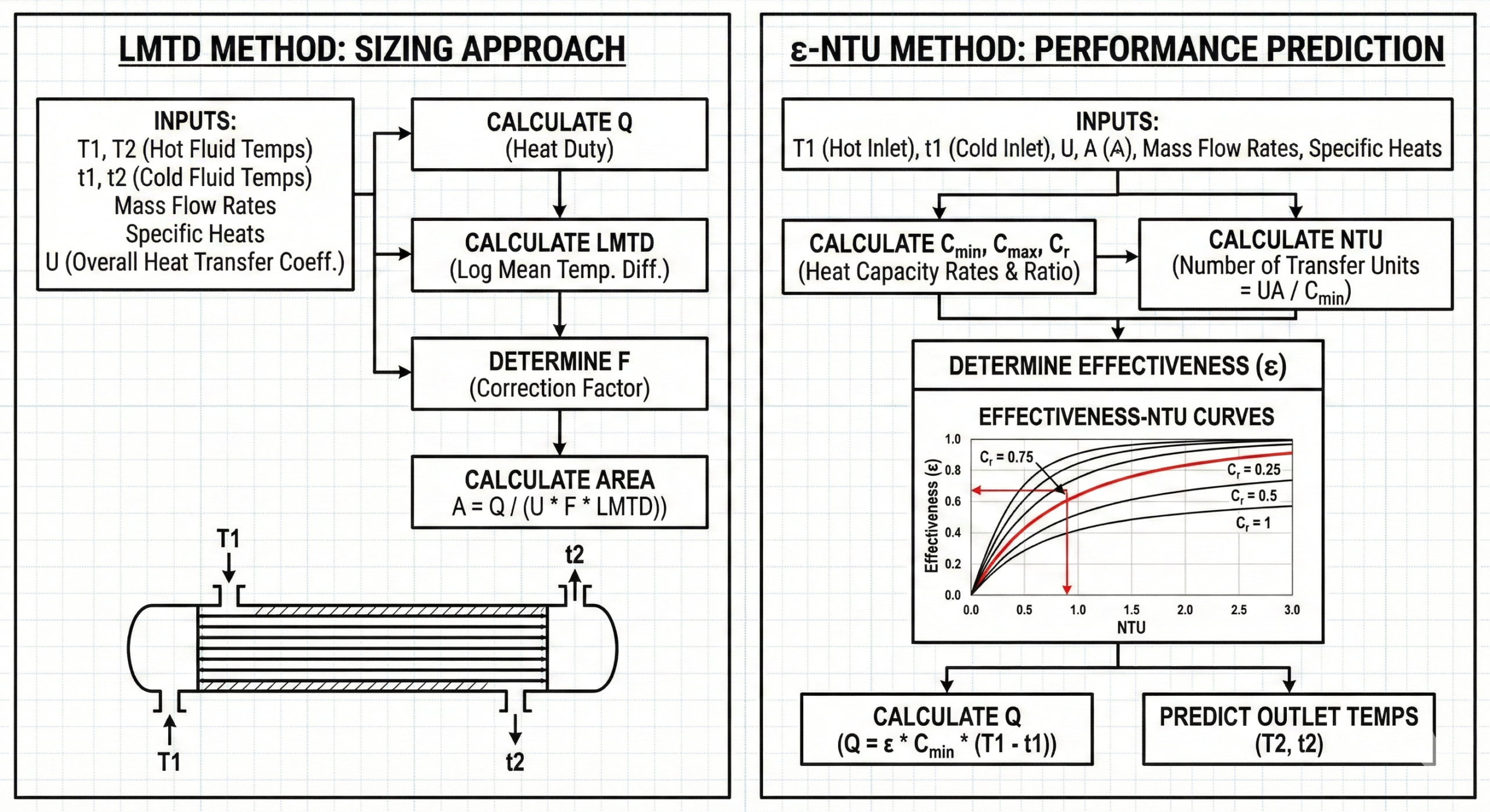
Comparison diagram showing difference between LMTD and epsilon-NTU methods for heat exchanger sizing and performance prediction
PPI March 12, 2026 0

LMTD vs ε-NTU – When Designers Should Switch – Choosing the Right Framework Instead of Forcing the Wrong One

LMTD and ε-NTU are not competing theories.They are two different ways of describing the same physical reality. Most problems in heat exchanger design do not come from using the wrong…

READ MORE +
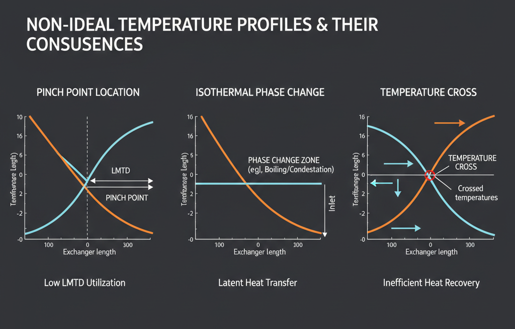
Diagram showing pinch point and phase change zones where LMTD becomes unreliable in heat exchangers
PPI March 11, 2026 0

When LMTD Fails – Phase Change & Pinch Points – The Situations Where a Reliable Tool Stops Being Reliable

LMTD is one of the most useful tools in heat exchanger design. Under the right conditions, it provides a compact and effective way to represent temperature driving force. However, LMTD…

READ MORE +
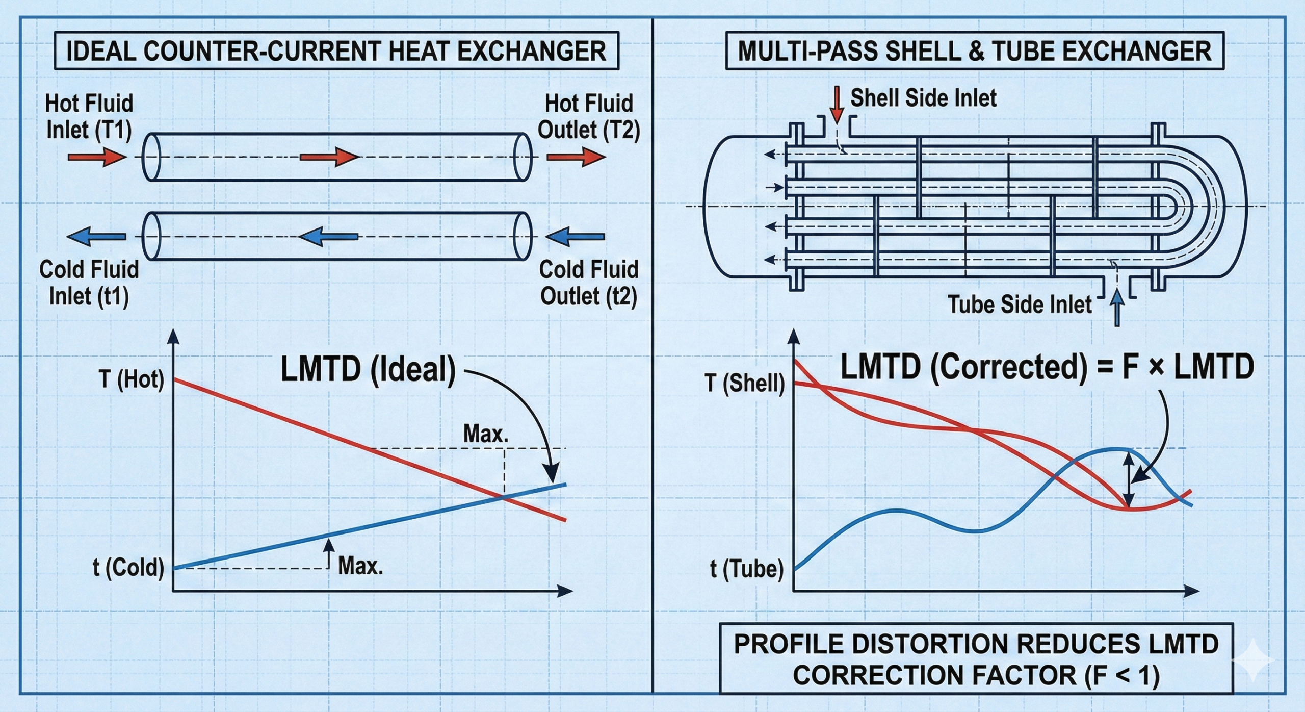
Diagram showing difference between ideal counter-current exchanger and real multi-pass exchanger requiring LMTD correction factor
PPI March 10, 2026 0

LMTD Correction Factor – Why It Exists – Because Real Heat Exchangers Are Not Ideal Counter-Current Devices

LMTD works perfectly for one ideal situation: true counter-current flow. In that arrangement, temperature driving force is distributed efficiently along the entire length of the exchanger, and the calculated LMTD…

READ MORE +
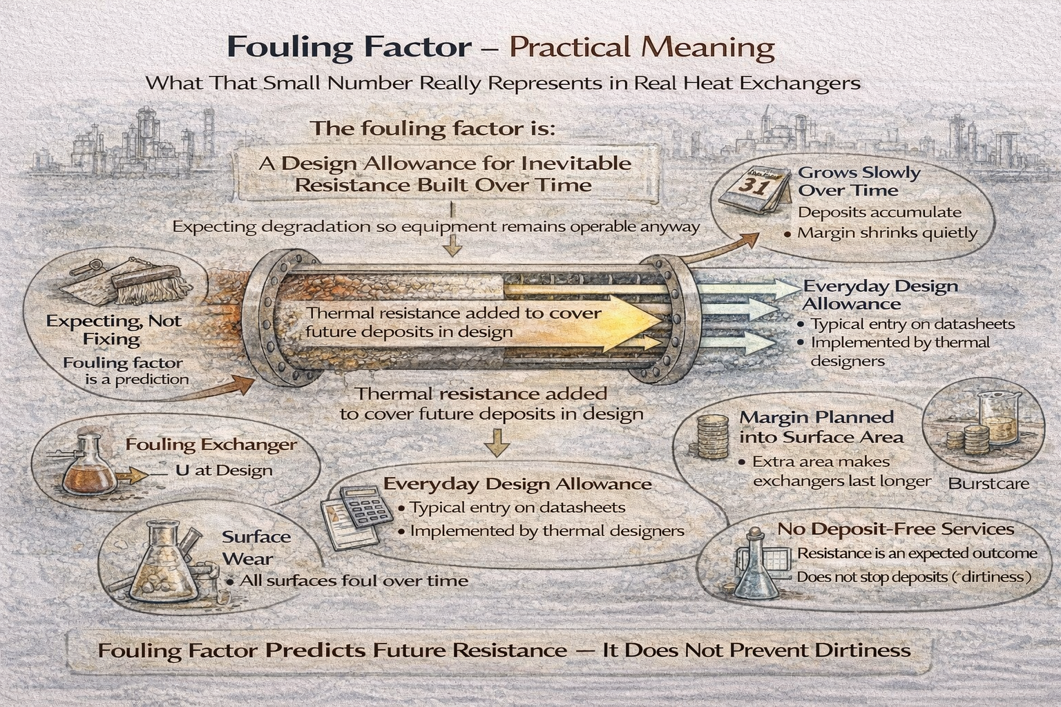
fouling factor in heat exchangers as added thermal resistance
PPI February 18, 2026 0

How Fouling Increases Thermal Resistance Over Time – What That Small Number Really Represents in Real Heat Exchangers

The fouling factor is one of the most misunderstood entries in a heat exchanger datasheet. It is often: In operating plants, however, the fouling factor is rarely understood for what…

READ MORE +
thermal resistance layers forming overall heat transfer coefficient U
PPI February 11, 2026 0

How U Is Built from Film + Wall + Fouling Resistances – Why the Overall Heat Transfer Coefficient Is Never Just One Thing

The overall heat transfer coefficient — U — is one of the most used numbers in heat exchanger design. Overall heat transfer coefficient resistance comes from fluid films, wall conduction,…

READ MORE +

Posts pagination

1 2 Next

Recent Posts

  • Tube Side vs Shell Side Pressure Drop – What Really Matters
  • Why Pressure Drop Limits Are Critical in Heat Exchanger Design
  • Pressure Drop & Hydraulic Limits in Heat Exchanger Design
  • Common Thermal Design Misjudgements in Heat Exchangers
  • Design Margin in Heat Exchanger Thermal Calculations

Recent Comments

No comments to show.

Archives

  • August 2026 (12)
  • July 2026 (9)
  • June 2026 (9)
  • May 2026 (15)
  • April 2026 (18)
  • March 2026 (18)
  • February 2026 (16)
  • January 2026 (12)
  • December 2025 (1)

Categories

  • Heat Exchanger
  • Heat Transfer
  • Terms & Conditions
  • Disclaimer
  • Privacy Policy
  • Contact

2026 processplantinsights.com | Blogging WordPress Theme by Legacy Themes