In process plants, heat transfer is usually discussed in terms of flowing fluids, heat exchangers, and utilities. Convection receives most of the attention because it is visible, adjustable, and strongly linked to operating conditions.
Conduction, by contrast, appears simple and passive. It involves no flow, no moving parts, and no control valves. Because of this, it is often treated as secondary.
In reality, conduction plays a decisive role in how process equipment behaves, especially during startups, shutdowns, low-flow operation, and long-term plant aging.
This article explains what conduction really means in process equipment, where it occurs, why it sometimes dominates plant behavior, and how misunderstanding it leads to recurring operational problems.
Table of Contents
What Conduction Means in Process Equipment
Conduction is the transfer of heat through solid material due to temperature difference.
In process plants, this solid material includes:
- vessel shells,
- exchanger tubes and tube sheets,
- pipe walls,
- nozzles and flanges,
- supports and structural members.
Whenever one side of a solid is at a different temperature than the other, heat flows through the material.
No fluid motion is required.
No operating decision is needed.
As long as the solid exists and a temperature difference exists, conduction occurs.
Why Conduction Matters Even When Fluids Are Not Moving
A common misconception is that heat transfer stops when flow stops.
In reality, conduction becomes more visible when flow stops.
Examples include:
- idle piping warming up or cooling down,
- shutdown vessels losing heat slowly,
- isolated equipment reaching ambient temperature,
- standby systems influencing active systems.
When convection is reduced or eliminated, conduction often becomes the dominant heat transfer mechanism.
This is why plants frequently observe unexpected temperature changes explained by conduction behavior in real plant during:
- shutdowns,
- long holds,
- low-load operation,
- winterization or summer idle periods.
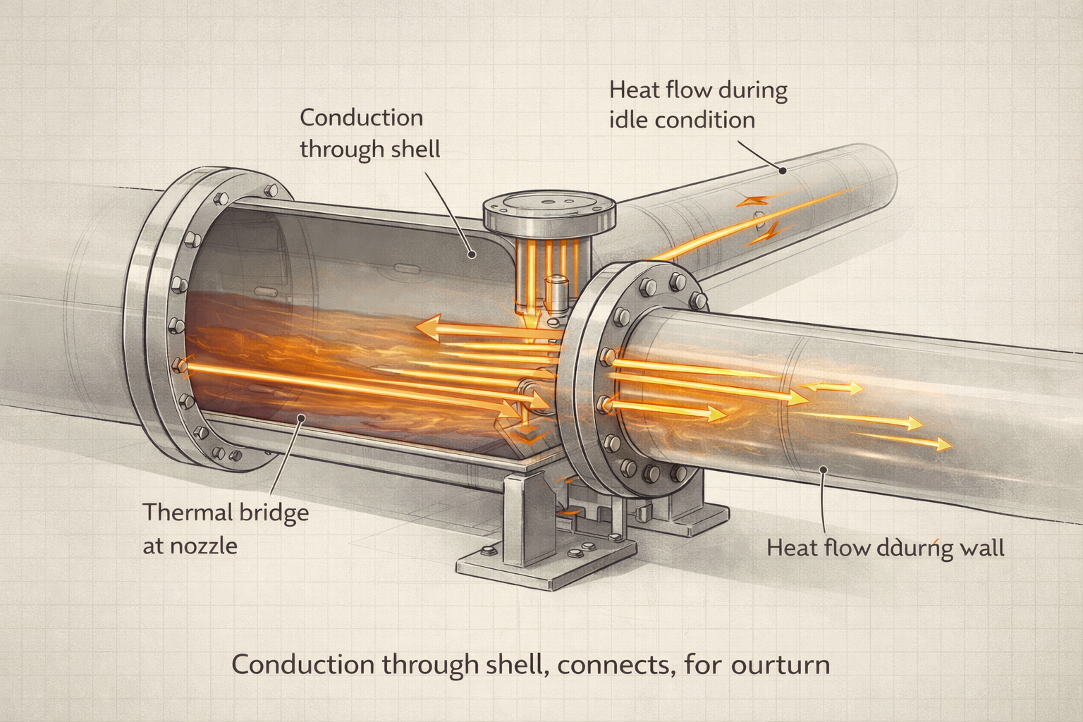
Where Conduction Occurs in Real Process Plants
Conduction occurs everywhere solids connect different thermal regions.
Common locations include:
Equipment Shells
Reactor shells, columns, and drums continuously conduct heat between process contents and surroundings.
Heat Exchanger Walls
Tubes and plates conduct heat between hot and cold fluids. This is intentional, but the resistance of the solid wall is often underestimated.
Piping Systems
Pipe walls conduct heat along the length of the line and radially to the environment, even when flow is stagnant.
Nozzles and Flanges
These act as thermal bridges, allowing heat to bypass insulation and migrate into connected equipment.
Supports and Structural Steel
Supports connect hot equipment to foundations and structures, providing additional conduction paths that are rarely considered explicitly.
Conduction Paths Engineers Commonly Ignore
Many conduction paths are not included in simplified design thinking.
Examples:
- heat flow through nozzle reinforcements and metal contact interfaces,
- conduction through instrument connections,
- heat leakage through pipe racks,
- temperature propagation through common headers.
These paths are usually small individually, but together they can:
- increase heat loss,
- alter temperature profiles,
- create condensation risks,
- influence adjacent equipment.
Plants often encounter these effects only after commissioning.
Metal Thickness and Heat Flow
One of the most misunderstood aspects of conduction is the role of thickness.
Thicker metal does not stop heat flow.
It increases thermal resistance within the solid wall.
This distinction matters.
A thick vessel wall:
- slows heat transfer,
- increases thermal inertia,
- delays temperature response.
But it does not prevent heat transfer.
This explains why:
- large vessels take longer to heat or cool,
- shutdown cooldown periods are extended,
- thermal stresses develop across thick sections.
Thickness changes rate, not direction.
Why Equipment Still Transfers Heat When Idle
Idle equipment is often assumed to be thermally inactive.
In reality:
- hot idle equipment continues to lose heat,
- cold idle equipment continues to gain heat,
- connected equipment influences each other thermally.
Conduction through metal ensures that temperature equalization continues until equilibrium is reached.
This is why:
- hot standby systems need continuous heat input,
- cold systems require protection against warming,
- isolation alone does not guarantee temperature stability.
Interaction Between Conduction and Convection
In most operating equipment, conduction and convection work together.
Examples:
- heat conducts through a tube wall, then convects into the fluid,
- heat convects from fluid to wall, then conducts outward to insulation,
- fouling adds resistance at the interface that can cancel the benefit of high-conductivity metals, magnifying the role of conduction.
When convection is strong, conduction may appear secondary.
When convection weakens, conduction often becomes the controlling step.
Understanding which mechanism dominates under which condition is essential for realistic analysis.
When Conduction Becomes the Dominant Mechanism
Conduction dominates heat transfer behavior in several common plant situations where solid resistance becomes the controlling mechanism:
- very low or zero flow conditions,
- thick-walled equipment,
- stagnant zones in vessels,
- insulated systems with poor convection,
- shutdown and startup transitions.
In these cases, increasing utility flow or adjusting control settings produces limited improvement, because the limiting resistance lies in the solid material.
Recognizing this prevents futile operational adjustments.
Conduction During Startup and Shutdown
Startups and shutdowns are inherently thermal events.
During these transitions:
- temperature gradients are steep,
- solids lag behind fluids,
- thermal stresses develop.
Conduction governs:
- how quickly equipment heats up,
- how uniformly temperature spreads,
- where stress concentrations form.
Poor understanding of conduction during transients leads to:
- cracking,
- gasket failures,
- distorted equipment,
- shortened equipment life.
Many mechanical failures attributed to “operation” originate in thermal conduction effects.
Why Insulation Does Not Eliminate Conduction
insulation reduces external heat loss but does not eliminate conduction through the metal wall within equipment.
Heat still conducts:
- through the metal wall,
- along the pipe length,
- into supports and nozzles.
This explains why:
- insulated equipment still shows temperature gradients,
- heat loss occurs at flanges and supports,
- insulation effectiveness varies with condition.
Insulation manages consequences of conduction; it does not remove the mechanism.
Long-Term Effects of Conduction on Plant Performance
Over time, conduction contributes to gradual performance changes:
- increased heat loss as insulation degrades,
- altered temperature profiles due to fouling,
- higher energy consumption to maintain conditions,
- thermal aging of equipment.
Because these effects develop slowly, they are often accepted as “normal.”
In reality, they represent unmanaged thermal behavior.
Plants that periodically reassess conduction paths maintain performance longer.
Operational Problems Rooted in Poor Conduction Understanding
Many recurring plant issues have conduction at their root:
- unexpected condensation in lines,
- cold spots causing corrosion,
- uneven heating during startup,
- difficulty maintaining standby temperatures,
- slow response to heating or cooling actions.
Treating these as control or maintenance problems often yields only temporary relief.
Addressing the underlying conduction behavior produces lasting improvement.
Design and Maintenance Implications
Understanding conduction influences better decisions during:
- equipment design,
- insulation specification,
- material selection,
- layout planning,
- maintenance prioritization.
Examples include:
- recognizing critical thermal bridges,
- selecting materials with appropriate conductivity,
- designing supports with thermal behavior in mind,
- planning controlled heating and cooling rates.
Conduction-aware design is more robust and forgiving in operation.
Why Conduction Matters to Plant Owners
From an ownership perspective, conduction affects:
- energy losses,
- startup time,
- maintenance cost,
- equipment life,
- safety margins.
Because conduction-driven losses are continuous, they quietly increase operating cost.
Improvements that manage conduction effectively often deliver:
- steady energy savings,
- improved reliability,
- reduced downtime.
Few mechanisms influence both cost and reliability as consistently as conduction.
Final Perspective
Conduction is not dramatic.
It does not fluctuate rapidly.
It does not announce itself.
Yet it governs how equipment warms, cools, stabilizes, and ages.
Plants that underestimate conduction often struggle with:
- slow transients,
- hidden heat losses,
- repeated thermal damage.
Plants that understand and respect conduction operate more predictably and age more gracefully.
This understanding is not advanced theory.
It is practical plant reality.
And it is essential for anyone responsible for process equipment performance.
Now that we understand how conduction behaves inside process equipment, the next step is to observe how this mechanism appears in everyday plant situations.
Many temperature changes in vessels, piping, and idle systems that seem unexpected are actually explained by simple conduction paths through metal structures.
Conduction Explained with Plant Examples
This article walks through real plant examples showing how conduction moves heat through vessel shells, piping, nozzles, supports, and idle equipment—even when nothing appears to be happening.
Explore the complete series in the Heat Transfer Engineering Hub.
A practicing chemical engineer with 17+ years of experience in process design, project execution, commissioning, and plant operations. Focused on practical engineering judgment beyond textbook explanations.