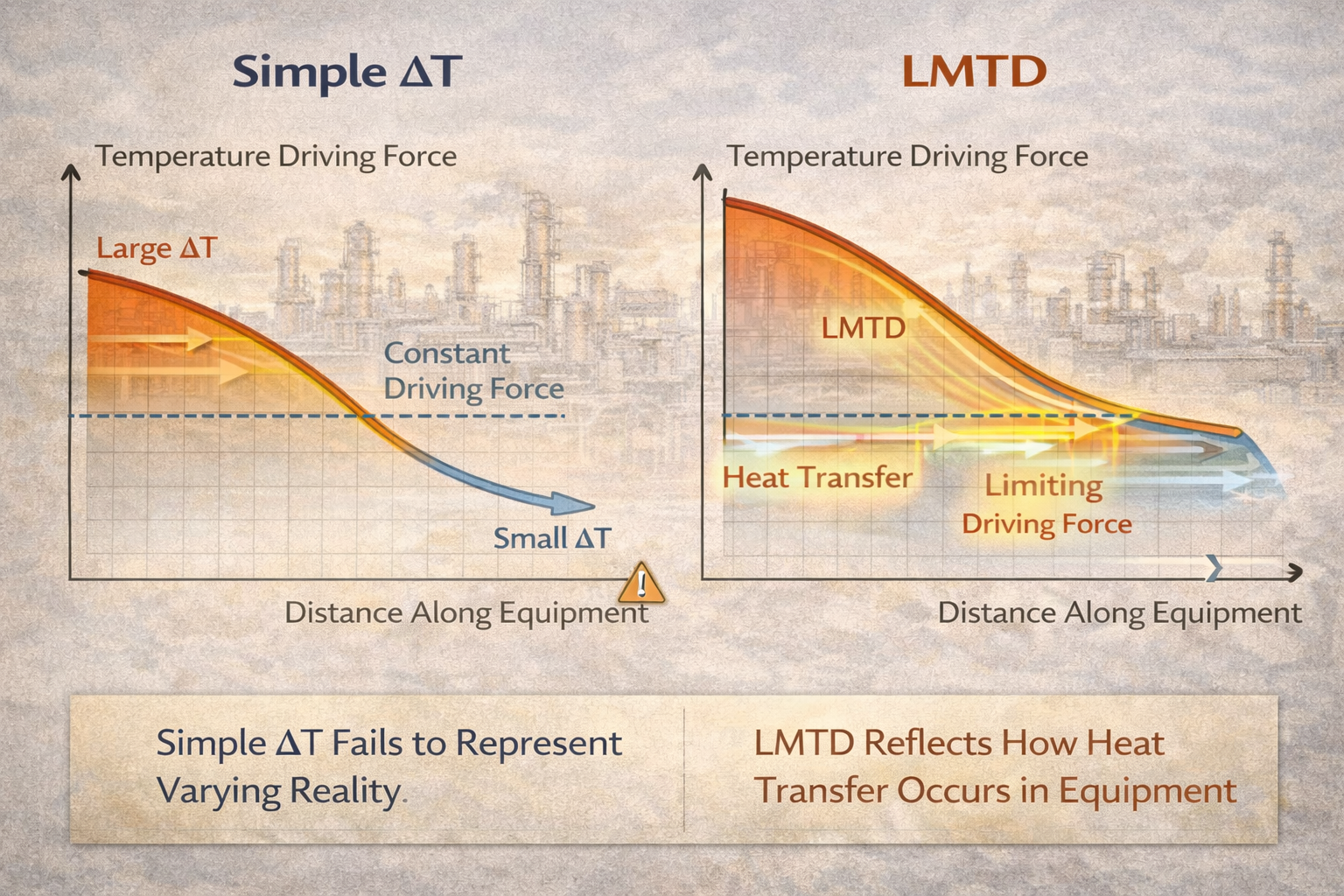
A simple temperature difference, ΔT, feels intuitive. Hot in minus cold out seems like a reasonable way to describe how strongly heat transfer is driven.
In real process equipment, however, heat transfer does not occur at a single temperature difference. It occurs along the length of equipment, under continuously changing conditions.
LMTD is used instead of simple ΔT because it reflects this reality. It transforms distributed temperature behavior into a usable engineering driving force.
Simple ΔT does not.
This article explains why simple ΔT fails to represent real exchanger behavior and why LMTD became the standard tool in process engineering.
Table of Contents
Simple ΔT Assumes Uniform Driving Force
Using a simple temperature difference assumes that:
- the driving force is constant,
- heat transfer rate is uniform,
- all parts of the exchanger contribute equally.
None of these assumptions hold in real exchangers.
In practice:
- ΔT is high at one end,
- ΔT is low at the other,
- heat transfer rate varies continuously.
Simple ΔT describes a condition that never actually exists inside the equipment.
Heat Transfer Is Strongest Where ΔT Is Highest
Heat transfer rate at any location depends on local temperature difference. This sensitivity becomes critical near pinch and temperature cross conditions.
Where ΔT is large:
- heat flux is high,
- energy transfer is efficient.
Where ΔT is small:
- heat flux collapses,
- resistance dominates,
- performance is constrained.
Simple ΔT gives equal weight to all regions, even though they contribute very differently to total heat transfer.
This is the core reason it fails.
Simple ΔT Hides the Limiting End of the Exchanger
Most exchangers are limited not by where ΔT is large, but by where ΔT is small.
Near the approach end:
- temperature difference becomes minimal,
- driving force collapses,
- capacity is determined.
Simple ΔT averages this critical low-ΔT region with high-ΔT regions, masking the true limitation.
LMTD, by contrast, is heavily influenced by the smallest temperature difference.
Why Arithmetic Averaging Is Physically Wrong
Arithmetic averaging assumes linear behavior.
Heat transfer does not behave linearly with ΔT along an exchanger.
Because heat transfer rate is proportional to local ΔT:
- regions with high ΔT contribute disproportionately more heat,
- regions with low ΔT restrict total transfer disproportionately.
Logarithmic averaging reflects this non-linear contribution.
Arithmetic averaging does not.
Simple ΔT Overestimates Real Driving Force
Because simple ΔT ignores the exponential decay of temperature difference, it usually:
- overestimates effective driving force,
- underestimates required area,
- gives false confidence about margin.
This explains why exchangers designed with simple ΔT:
- struggle near design conditions,
- lose capacity rapidly with fouling,
- show unstable control near limits.
LMTD reduces this optimism by representing effective, not apparent, driving force.
LMTD Preserves Total Heat Transfer Correctly
LMTD answers a very specific question:
What single constant temperature difference would produce the same total heat transfer as the actual varying temperature difference?
Simple ΔT cannot answer this question.
LMTD does not claim that ΔT is constant.
It produces a mathematically equivalent constant that preserves total heat transfer behavior.
That is why it works for sizing and comparison.
Flow Arrangement Makes Simple ΔT Meaningless
In counter-current, co-current, and cross-flow exchangers:
- temperature profiles differ radically,
- minimum ΔT occurs in different locations,
- performance changes significantly.
Simple ΔT cannot distinguish these cases reliably.
LMTD automatically accounts for:
- flow direction,
- relative temperature approach,
- effectiveness of arrangement.
This is why exchanger orientation matters — and why LMTD reflects it. Real exchangers therefore require correction factors to account for non-ideal geometry.
Simple ΔT Breaks Down Near Pinch Conditions
As exchangers approach pinch:
- one terminal ΔT approaches zero,
- effective driving force collapses,
- performance becomes highly sensitive.
Simple ΔT hides this collapse until failure occurs.
LMTD collapses sharply as minimum ΔT shrinks, correctly signaling:
- loss of margin,
- instability,
- high fouling sensitivity.
This behavior makes LMTD a better warning indicator. Even so, severe pinch conditions may still require alternative exchanger analysis methods.
Why Engineers Still Sometimes Use Simple ΔT
Simple ΔT is sometimes used:
- for quick screening,
- for rough comparisons,
- in early conceptual discussions.
When used this way, it must be treated as:
- indicative,
- optimistic,
- non-limiting.
Problems arise when simple ΔT is used as a design or operating criterion.
Why LMTD Is Still Not Perfect
Although LMTD is superior to simple ΔT, it has limits:
- it assumes steady-state,
- it assumes single-phase flow,
- it assumes smooth profiles.
That is why:
- correction factors exist,
- ε-NTU methods are used in some cases,
- LMTD fails under phase change or temperature cross.
LMTD is a better approximation, not an absolute truth. Its limitations become most visible during phase change and thermodynamic feasibility limits.
Owner Perspective: Why This Choice Matters
From an ownership standpoint, choosing LMTD over simple ΔT:
- reduces undersizing risk,
- improves reliability,
- prevents false confidence in revamps,
- avoids repeated debottlenecking failures.
Simple ΔT looks cheaper on paper.
LMTD is cheaper over the life of the plant.
Final Perspective
Simple ΔT is intuitive — and misleading.
LMTD exists because real heat transfer is uneven, non-linear, and constrained by minimum driving force.
Using LMTD is not about mathematical sophistication.
It is about respecting how heat actually moves inside equipment.
Engineers who understand this distinction design exchangers that work on paper and in plants.
Those who ignore it often discover the difference only after startup.
LMTD works best for ideal counter-current exchangers, but most real exchangers do not behave ideally.
Multiple passes, cross-flow arrangements, and flow mixing distort temperature profiles and reduce effective driving force.
LMTD Correction Factor – Why It Exists
This article explains why correction factors are required for real exchanger geometry and how non-ideal flow reduces thermal effectiveness.
Explore the complete series in the Heat Transfer Engineering Hub.

A practicing chemical engineer with 17+ years of experience in process design, project execution, commissioning, and plant operations. Focused on practical engineering judgment beyond textbook explanations.