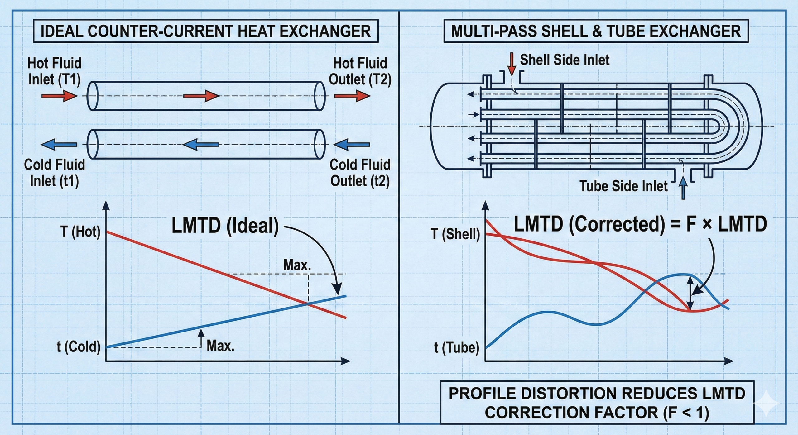
LMTD works perfectly for one ideal situation: true counter-current flow.
In that arrangement, temperature driving force is distributed efficiently along the entire length of the exchanger, and the calculated LMTD accurately represents reality.
Most real heat exchangers, however, are not true counter-current.
They involve:
- multiple shell passes,
- multiple tube passes,
- cross-flow sections,
- flow mixing and maldistribution.
The correction factor exists because of this gap between ideal theory and real equipment geometry.
Table of Contents
What the Correction Factor Actually Does
The correction factor modifies the ideal counter-current LMTD to reflect how real flow arrangements reduce effective temperature driving force.
In simple terms:
Corrected LMTD = Ideal Counter-Current LMTD × Correction Factor
The correction factor does not fix heat transfer problems.
It acknowledges that some driving force is lost due to geometry.
Why Ideal Counter-Current Is the Benchmark
Counter-current flow:
- maintains higher temperature difference along the exchanger,
- avoids early driving-force collapse,
- uses available surface area efficiently.
Because it represents the best possible arrangement, it is used as the reference case.
Any real arrangement that deviates from true counter-current must be corrected downward.
That downward adjustment is the correction factor.
Where Non-Ideal Flow Comes From
Most exchangers deviate from ideal behavior due to practical constraints:
- mechanical design limitations
- pressure drop constraints
- maintenance access requirements
- fabrication cost
- space availability
Examples include:
- 1–2 shell-and-tube exchangers
- multi-pass tube bundles
- cross-flow exchangers
- compact exchangers with mixed flow
Each deviation distorts the temperature profile.
How Geometry Distorts Temperature Profiles
In non-ideal exchangers:
- some fluid streams partially mix,
- temperature changes occur unevenly,
- local driving force collapses earlier than expected.
As a result:
- some surface area becomes underutilized,
- pinch points appear prematurely,
- effective heat transfer drops.
The correction factor accounts for this loss of utilization, not for fouling or poor operation.
Why the Correction Factor Is Always Less Than 1
A correction factor of 1 would mean:
- the exchanger behaves exactly like ideal counter-current flow.
In reality:
- mixing reduces temperature difference,
- flow reversals degrade profiles,
- cross-flow introduces inefficiencies.
Therefore:
- correction factor ≤ 1 always.
Values close to 1 indicate good thermal utilization.
Low values indicate poor geometry effectiveness.
What the Correction Factor Is Not
The correction factor is often misunderstood.
It does not represent:
- fouling
- safety margin
- design conservatism
- heat transfer coefficient degradation
It purely reflects flow arrangement and temperature profile distortion.
Using it to “absorb” fouling or uncertainty is a design error.
Why Low Correction Factors Are Dangerous
Designs with low correction factors often appear acceptable on paper but behave poorly in plants.
When the correction factor is low:
- effective driving force collapses quickly,
- exchanger becomes highly sensitive to fouling,
- small disturbances cause large performance loss,
- control stability suffers.
This is why many guidelines discourage designs with very low correction factors.
Low correction factor = fragile exchanger.
Why Fouling Makes Correction Factor Problems Worse
Correction factor loss and fouling interact multiplicatively.
As fouling increases:
- required driving force increases,
- effective LMTD shrinks further,
- pinch occurs earlier.
An exchanger that looks adequate when clean becomes unusable quickly if:
- correction factor is already marginal.
This explains why some exchangers “age badly” despite meeting design duty initially.
Correction Factor and Debottlenecking Failures
Many debottlenecking projects fail because:
- only surface area is added,
- flow arrangement remains unchanged,
- correction factor stays low.
Without improving geometry:
- added area delivers diminishing returns,
- temperature cross risk increases,
- operating margin remains poor.
Correction factor limits what area addition can achieve.
Why Designers Set Minimum Acceptable Values
Experienced designers rarely accept very low correction factors.
This is not conservatism.
It is recognition of operational reality.
Minimum limits exist because:
- real plants do not operate at clean, steady conditions,
- fouling and maldistribution are inevitable,
- temperature profiles degrade over time.
Correction factor margin is operational robustness, not theoretical elegance.
Why Operators Should Care About Correction Factor
Although operators do not calculate correction factors daily, they feel their consequences.
Symptoms of low correction factor designs include:
- outlet temperature stuck near approach,
- strong sensitivity to minor fouling,
- unstable temperature control,
- poor response to increased utility flow.
These are geometry problems, not operational mistakes.
Owner Perspective: Why the Correction Factor Protects Capital
From an ownership standpoint, ignoring correction factor leads to:
- exchangers that meet design duty briefly,
- rapid performance decline,
- repeated cleaning cycles,
- costly revamps that underdeliver.
Respecting correction factor during design:
- improves long-term reliability,
- reduces maintenance frequency,
- protects throughput.
The correction factor is an economic safeguard disguised as a thermal parameter.
Final Perspective
The correction factor exists because real exchangers are compromises.
It does not punish bad design.
It reveals the cost of non-ideal geometry.
Engineers who respect correction factor limits design exchangers that remain stable, forgiving, and operable over time.
Those who treat it as a mathematical inconvenience often discover its importance only after startup.
Understanding why the correction factor exists turns LMTD from a formula into a realistic design tool — and that understanding is essential for reliable heat exchanger performance in real process plants.
Explore the complete series in the Heat Transfer Engineering Hub.

A practicing chemical engineer with 17+ years of experience in process design, project execution, commissioning, and plant operations. Focused on practical engineering judgment beyond textbook explanations.