LMTD — Log Mean Temperature Difference — is one of the most widely used concepts in heat exchanger design and analysis. It appears simple in formula form, yet it is often applied mechanically, without understanding what it actually represents inside real equipment.
This article explains LMTD step by step, focusing not on the mathematics, but on the physical logic behind it. The goal is to make LMTD intuitive, so it can be used correctly — and questioned when necessary.
Table of Contents
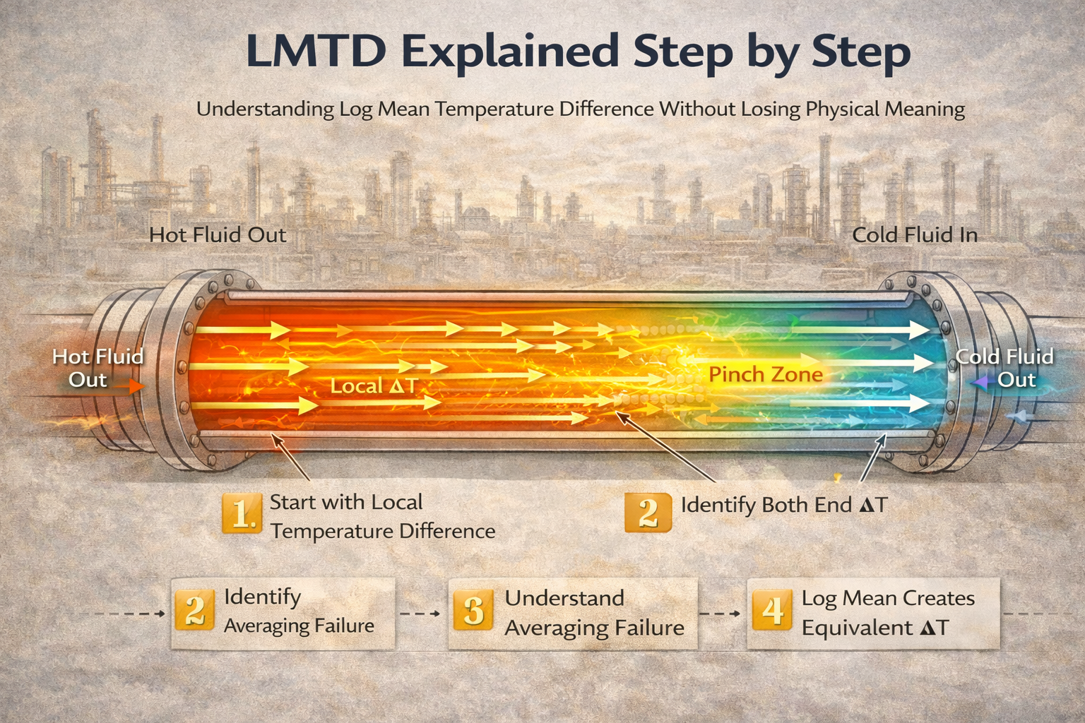
Step 1: Start with the Real Driving Force — Local Temperature Difference
Heat transfer does not occur at a single location or at a single temperature difference.
At every point along a heat exchanger:
- one fluid is hotter,
- the other is colder,
- heat flows according to the local temperature difference.
This local difference:
- is large near one end of the exchanger,
- small near the other end,
- continuously changes in between.
There is no single “true” ΔT for the whole exchanger.
Step 2: Recognize That Heat Transfer Is Uneven Along the Length
Because temperature difference changes with position:
- heat transfer rate is high where ΔT is large,
- heat transfer rate is low where ΔT is small.
This means:
- most heat is transferred in regions with high driving force,
- overall capacity is limited by regions with low driving force.
Any meaningful measure of driving force must reflect this uneven contribution.
Step 3: Identify the Two End Temperature Differences
Instead of tracking temperature difference everywhere, engineers identify the two terminal temperature differences:
- ΔT₁ → temperature difference at one end of the exchanger
- ΔT₂ → temperature difference at the other end
These two values define:
- the maximum available driving force,
- the minimum available driving force.
Everything that happens inside the exchanger lies between these two limits.
Step 4: Understand Why Simple Averaging Does Not Work
A simple arithmetic average of ΔT₁ and ΔT₂ assumes:
- heat transfer varies linearly,
- both ends contribute equally.
In reality:
- regions with high ΔT contribute disproportionately more heat,
- regions with low ΔT strongly restrict total transfer.
Simple averaging:
- overvalues low-contribution regions,
- undervalues high-contribution regions.
This produces misleading results, especially near pinch conditions.
Step 5: Why a Logarithmic Mean Is Used
The logarithmic mean is used because it:
- weights temperature difference according to its contribution to heat transfer,
- reflects exponential decay of driving force along the exchanger,
- preserves correct total heat transfer behavior.
LMTD mathematically represents:
The single constant temperature difference that would produce the same total heat transfer as the actual varying temperature difference.
It is not a physical temperature.
It is an equivalent driving force.
Step 6: What LMTD Physically Represents
LMTD answers this question:
If the exchanger operated everywhere at one constant ΔT, what value of ΔT would give the same total heat transfer?
This makes LMTD:
- a modeling tool,
- a design convenience,
- a way to collapse spatial variation into one usable number.
It does not represent:
- minimum ΔT,
- maximum ΔT,
- local metal temperature,
- safety margin.
Step 7: Apply LMTD Only to Steady, Single-Phase Conditions
LMTD works best when:
- both fluids remain single phase,
- flow is steady,
- temperature profiles are smooth,
- no internal pinch exists.
Under these conditions:
- temperature difference varies predictably,
- logarithmic averaging is valid,
- LMTD gives reliable sizing results.
Outside these conditions, LMTD must be questioned.
Step 8: Understand How Flow Arrangement Affects LMTD
The same inlet and outlet temperatures can produce different LMTD values depending on flow arrangement.
- Counter-current flow maintains higher ΔT along the length
- Co-current flow loses driving force rapidly
- Cross-flow requires correction
This explains why:
- counter-current exchangers are smaller,
- co-current exchangers struggle near outlet,
- correction factors exist for real geometries.
LMTD reflects how fluids meet, not just how hot they are.
Step 9: Why LMTD Shrinks Faster Than Expected
As exchangers approach pinch:
- ΔT₂ becomes very small,
- logarithmic averaging collapses rapidly,
- effective driving force disappears.
This explains why:
- small fouling causes large duty loss,
- exchangers become sensitive near limits,
- control becomes unstable close to approach temperatures.
LMTD is dominated by the smallest ΔT, not the largest.
Step 10: What LMTD Does Not Tell You
LMTD does not reveal:
- where pinch occurs,
- local hot spots,
- peak heat flux,
- metal temperature limits,
- transient behavior.
It tells you:
- total driving force for steady-state heat transfer.
Using LMTD alone without profile awareness is incomplete engineering.
Common Misuses of LMTD in Plants
Some frequent mistakes include:
- assuming higher LMTD guarantees safe operation,
- using LMTD to judge fouling severity directly,
- applying LMTD to phase-change zones blindly,
- ignoring correction factors.
These errors usually trace back to misunderstanding what LMTD represents.
How Experienced Engineers Use LMTD Correctly
In practice, experienced engineers:
- use LMTD for initial sizing,
- check minimum temperature difference separately,
- examine temperature profiles,
- apply conservative margins,
- switch methods when conditions demand it.
LMTD is used as a framework, not as a final answer.
Owner Perspective: Why This Understanding Matters
From an ownership standpoint, misunderstanding LMTD leads to:
- exchangers that look adequate on paper but fail in service,
- repeated cleaning without capacity recovery,
- expensive revamps that do not solve bottlenecks.
Understanding LMTD properly:
- prevents false confidence,
- supports realistic debottlenecking,
- protects capital investment.
Final Perspective
LMTD is not a formula to memorize.
It is a compact representation of a complex, distributed reality.
Used thoughtfully, it is powerful.
Used blindly, it is misleading.
Understanding LMTD step by step replaces mechanical calculation with physical insight — and that is the difference between exchangers that merely “meet design” and exchangers that perform reliably in real process plants.
Knowing the required heat duty tells us how much heat must be transferred,
but it does not explain how temperature difference actually drives that heat
flow along real equipment.
The next step is to understand why a simple temperature difference is not
sufficient and why engineers rely on LMTD instead.
Why LMTD Is Used Instead of Simple ΔT
This article explains why temperature driving force changes along equipment
length, how LMTD captures this behavior, and why using a simple ΔT often leads
to incorrect sizing and performance assessment.

A practicing chemical engineer with 17+ years of experience in process design, project execution, commissioning, and plant operations. Focused on practical engineering judgment beyond textbook explanations.