The overall heat transfer coefficient — U — is one of the most used numbers in heat exchanger design.
Overall heat transfer coefficient resistance comes from fluid films, wall conduction, and fouling layers acting together.
But it is also one of the most misunderstood.
Many engineers speak about U as if it were a single property:
- “The exchanger has low U.”
- “We need a higher U service.”
- “U should be around 300.”
In reality, U is not a single resistance.
U is the combined outcome of multiple thermal resistances acting together.
To understand U properly, one must understand what builds it:
- Fluid films on both sides
- Metal wall resistance
- Fouling resistance over time
This article explains step by step how U is formed from these layers, and why the smallest resistance is rarely the problem — the largest one is.
Table of Contents
Heat Transfer Is Always a Resistance Network
Heat does not move freely.
Even in the best exchanger, heat must pass through barriers.
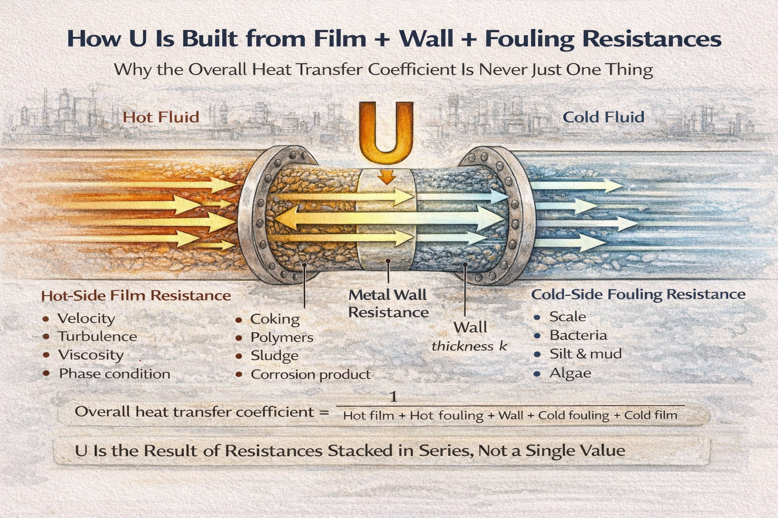
Whenever heat flows from a hot fluid to a cold fluid, it crosses a chain of resistances:
- Hot fluid film
- Hot-side fouling
- Metal wall
- Cold-side fouling
- Cold fluid film
Each one adds difficulty.
So heat transfer is similar to electrical current:
- Temperature difference is like voltage
- Heat flow is like current
- Thermal resistance is like electrical resistance
And U is simply the inverse of total resistance.
The Key Concept: Heat Sees the Total Resistance
Heat does not care whether the resistance comes from:
- slow-moving oil,
- scale deposits,
- thick tube walls,
- low turbulence water,
- polymer buildup.
All heat experiences is:
“How hard is it to get from hot fluid to cold fluid?”
That “difficulty” is total resistance.
And U represents that total difficulty.
So when U drops, it is always because:
Some resistance in the chain increased.
Resistance #1: Hot Fluid Film Resistance
The first barrier heat faces is the thin stagnant layer of fluid near the wall.
Even if a fluid is flowing fast, the layer touching the metal surface moves slowly.
This creates film resistance.
Hot-side film resistance depends on:
- velocity
- turbulence
- viscosity
- phase condition
Plant example
Hot crude oil being cooled has high viscosity.
Even with large area, heat transfer is limited because:
- oil film resistance dominates
- turbulence is weak
- convection is poor
This produces low hot-side heat transfer coefficient.
In such cases, no wall material upgrade helps much — because the fluid film is the bottleneck.
Resistance #2: Hot-Side Fouling Resistance
Over time, deposits form on the hot surface.
These may be:
- coke precursors
- polymer films
- organic sludge
- corrosion product redeposition
Even a thin layer behaves like insulation.
Fouling resistance grows silently and steadily.
This is why exchangers meet duty after cleaning, then lose performance months later.
Fouling is not an event.
It is a time-dependent resistance buildup.
Resistance #3: Metal Wall Resistance
Once heat crosses the hot-side surface, it enters the metal wall.
Wall resistance depends on:
- wall thickness
- thermal conductivity of metal
Most metals conduct heat well.
So wall resistance is often small compared to fluid films.
But not always.
When wall resistance matters
- thick tube sheets
- low-conductivity alloys
- heavily corroded walls
- specialized materials (stainless vs carbon steel)
In very high-performance exchangers, wall resistance becomes noticeable.
But in most plant exchangers, wall resistance is not the limiting factor.
The fluids usually dominate.
Resistance #4: Cold-Side Fouling Resistance
Cold-side fouling is extremely common in utilities.
Cooling water deposits include:
- calcium carbonate scaling
- biological growth
- silt and mud
- algae films
Even when hot-side is clean, cold-side fouling can cut U drastically.
Cooling water exchangers often show:
- seasonal underperformance
- rising pressure drop
- frequent cleaning cycles
Cold-side fouling is often more severe because cooling water systems are shared, open, and contamination-prone.
Resistance #5: Cold Fluid Film Resistance
Finally, heat must enter the cold fluid through another film layer.
Cold-side coefficients are often higher for water services.
But they drop when:
- flow is low
- maldistribution occurs
- laminar regime develops
- gas cooling is involved
Plant example
Air coolers have very low cold-side coefficients because air is a poor heat transfer medium.
So even with large finned area, U remains limited.
This is why air coolers are huge compared to water coolers.
How All Resistances Combine Into Overall U
All resistances add in series.
So total resistance is:
Hot film + Hot fouling + Wall + Cold fouling + Cold film
U is defined as:
Overall heat transfer coefficient = 1 / Total resistance
This explains the most important reality:
The largest resistance controls U
If fouling dominates, U is low.
If oil film dominates, U is low.
If gas-side dominates, U is low.
Improving small resistances does nothing if the dominant resistance is untouched.
Why U Changes Even When Equipment Does Not
Many operators ask:
- “Why did U drop suddenly?”
- “Why was U higher last month?”
Because resistances change:
- fouling builds
- flow rates shift
- viscosity changes
- turbulence changes
- maldistribution evolves
So U is not fixed.
U reflects operating history.
Why Cleaning Restores U Only Temporarily
Cleaning removes fouling resistance.
So total resistance drops.
U rises again.
But:
- film resistances remain
- wall resistance remains
- fouling returns
Therefore, U recovery is always temporary unless root causes are addressed.
Cleaning resets one layer, not the entire chain.
Practical Insight: U Is Not a Number — It Is a Story
Every U value tells a story:
- Which side is limiting?
- Is fouling dominating?
- Is flow too low?
- Is phase change involved?
- Is maldistribution wasting area?
A low U is not a failure.
It is a resistance diagnosis.
Owner Perspective: Why This Breakdown Matters
Owners often focus on one question:
- “Why is exchanger performance declining?”
Understanding resistance layers clarifies:
- where money is being lost
- whether cleaning will help
- whether redesign is needed
- whether utility system is the bottleneck
Instead of chasing U blindly, plants can target the real resistance.
Final Perspective
Overall heat transfer coefficient is not mysterious.
It is simply the inverse of total resistance.
And total resistance is built from:
- fluid films
- wall conduction
- fouling layers
Engineers who understand this stop treating U as a design guess.
They start treating U as what it truly is:
The plant’s thermal resistance fingerprint.
That understanding is the foundation of reliable heat exchanger design and operation.
We have discussed what the overall heat transfer coefficient really means in
plant operation and why it is never a single fixed property of an exchanger.
What Really Controls U in Exchangers
This article explains how convection films, metal walls, and fouling layers
combine to form the overall U value — and why the controlling resistance is
rarely the one engineers assume.
A practicing chemical engineer with 17+ years of experience in process design, project execution, commissioning, and plant operations. Focused on practical engineering judgment beyond textbook explanations.