
Understanding the Three-Letter Code Is Easy—Selecting the Right One Requires Engineering Judgment
If you open heat exchanger datasheets from different projects, you’ll repeatedly encounter TEMA designations such as:
- BEM
- BEU
- AES
- AET
To a new engineer, these combinations often appear to be model numbers.
They are not.
Each three-letter code is simply a shorthand description of the exchanger’s mechanical construction.
For example, BEM tells an experienced engineer:
- what type of front head is used,
- what shell arrangement is selected,
- how the rear head accommodates thermal expansion,
- how the exchanger can be cleaned,
- and what kind of services it is best suited for.
That is why selecting the correct TEMA type is much more than choosing a standard configuration.
It is about matching the exchanger’s mechanical design with the realities of plant operation.
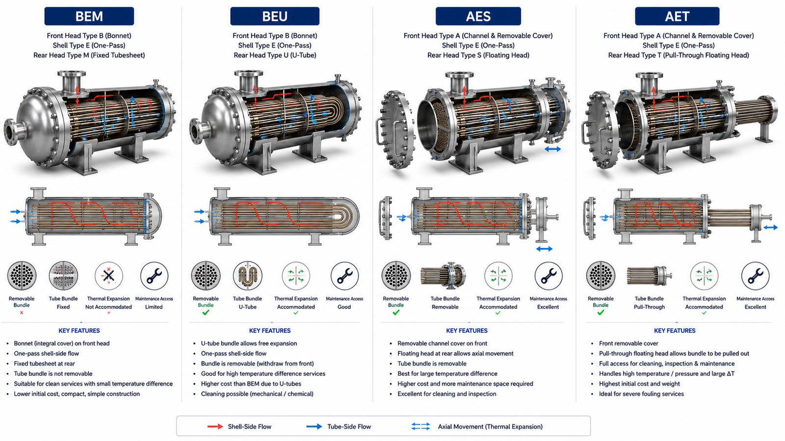
This article compares four of the most common TEMA configurations—BEM, BEU, AES, and AET—and explains when each one makes engineering sense.
Table of Contents
What Does a TEMA Code Actually Mean?
Every Letter Has a Different Purpose
A TEMA designation contains three letters.
Each letter identifies a different section of the exchanger.
First Letter
The front head (stationary head)
Examples:
- A
- B
- C
Second Letter
The shell type
Examples:
- E
- F
- G
- J
- K
Third Letter
The rear head
Examples:
- M
- U
- S
- T
Together, these three letters completely describe the exchanger’s basic mechanical construction.
Why Comparing Complete TEMA Types Is Important
Engineers Do Not Select Individual Letters Separately
In theory, engineers choose:
- front head
- shell
- rear head
individually.
In practice, certain combinations have become industry standards because they perform well in specific services.
For example:
- BEM
- BEU
- AES
- AET
appear repeatedly across refineries, chemical plants, fertilizer units, and petrochemical complexes.
Understanding these complete configurations makes exchanger selection much easier.
BEM – The Standard Fixed Tubesheet Exchanger
Construction
BEM consists of:
- B – Bonnet front head
- E – One-pass shell
- M – Fixed tubesheet rear head
It is one of the simplest shell-and-tube exchanger configurations.
Why Engineers Select BEM
BEM is chosen when:
- shell-side cleaning is unnecessary
- thermal expansion is relatively small
- fluids remain reasonably clean
- low equipment cost is important
Because the tube bundle is permanently attached to the shell, fabrication is straightforward.
Typical Applications
BEM exchangers are commonly used for:
- cooling water systems
- utility exchangers
- lube oil coolers
- clean liquid heating
- non-fouling process streams
Advantages
- Lowest fabrication cost
- Simple construction
- Good mechanical strength
- Minimal gasket joints
- Easy fabrication
Limitations
The fixed tubesheet creates important restrictions.
The tube bundle:
- cannot be removed
- limits shell-side cleaning
- offers limited flexibility for large thermal expansion
These limitations should always be considered before selecting BEM.
BEU – The Economical Choice for High Thermal Expansion
Construction
BEU consists of:
- B – Bonnet front head
- E – One-pass shell
- U – U-tube rear head
Instead of allowing a floating tubesheet, thermal expansion is absorbed by the curved tubes.
Why Engineers Select BEU
BEU becomes attractive when:
- shell and tube temperatures differ significantly
- thermal expansion must be accommodated
- removable tube bundles are desirable
- lower cost than floating head construction is preferred
It provides excellent thermal flexibility without the complexity of a floating head.
Typical Applications
BEU exchangers are frequently used in:
- steam heaters
- refinery process exchangers
- condensers
- hot utility services
- high-temperature liquid cooling
Advantages
- Excellent thermal expansion capability
- Removable tube bundle
- Lower cost than floating head designs
- Fewer sealing surfaces
Limitations
The U-shaped tubes introduce some disadvantages.
Individual tubes are:
- more difficult to replace
- harder to mechanically clean near the bend
Therefore, BEU is less attractive when severe tube-side fouling is expected.
AES – Maximum Maintenance Accessibility
Construction
AES consists of:
- A – Channel with removable cover
- E – One-pass shell
- S – Floating head rear arrangement
This configuration is designed for demanding industrial services.
Why Engineers Select AES
AES offers excellent maintenance flexibility.
The exchanger allows:
- mechanical tube cleaning
- removable tube bundle
- shell-side inspection
- accommodation of thermal expansion
It is one of the most versatile TEMA arrangements.
Typical Applications
AES exchangers are widely used in:
- crude oil preheat trains
- refinery units
- petrochemical plants
- fouling hydrocarbon services
- high-maintenance process duties
Advantages
- Excellent maintenance accessibility
- Suitable for severe fouling
- Floating head absorbs thermal expansion
- Tube bundle can be removed
Limitations
These advantages increase:
- fabrication cost
- equipment complexity
- number of gasket joints
AES is therefore selected only when the service justifies its higher lifecycle value.
AET – Maximum Accessibility with Pull-Through Floating Head
Construction
AET consists of:
- A – Channel with removable cover
- E – One-pass shell
- T – Pull-through floating head
It represents one of the most maintenance-friendly shell-and-tube exchanger configurations.
Why Engineers Select AET
The pull-through floating head allows the complete tube bundle to be removed more easily during shutdowns.
This reduces maintenance time.
The design is especially valuable in services requiring frequent inspection and cleaning.
Typical Applications
AET exchangers are commonly selected for:
- refinery process units
- severe fouling services
- heavy hydrocarbon cooling
- high-maintenance exchangers
Advantages
- Excellent maintenance access
- Easy bundle removal
- Handles thermal expansion effectively
- Suitable for repeated cleaning
Limitations
Compared with AES, AET generally involves:
- higher fabrication cost
- larger rear head
- additional installation space
Plants usually accept these penalties only when maintenance savings justify them.
Comparing the Four TEMA Types
| TEMA Type | Front Head | Rear Head | Bundle Removable | Thermal Expansion | Typical Service |
|---|---|---|---|---|---|
| BEM | Bonnet | Fixed Tubesheet | No | Limited | Clean utility services |
| BEU | Bonnet | U-Tube | Yes | Excellent | High-temperature services |
| AES | Removable Channel | Floating Head | Yes | Excellent | Fouling process services |
| AET | Removable Channel | Pull-Through Floating Head | Yes | Excellent | Severe fouling and frequent maintenance |
The comparison highlights an important principle:
As maintenance flexibility increases, construction complexity and capital cost also increase.
How Engineers Select Between These Four Configurations
Step 1 – Is Thermal Expansion Significant?
If shell and tube temperatures differ greatly:
Avoid BEM.
Consider:
- BEU
- AES
- AET
Step 2 – Is Shell-Side Cleaning Required?
If shell-side fouling is expected:
Avoid fixed tubesheet construction.
Choose a removable bundle design.
Step 3 – How Often Will the Exchanger Be Opened?
If shutdown maintenance is frequent:
AES or AET often become economical despite their higher purchase cost.
If cleaning is rare:
BEM or BEU may provide lower lifecycle cost.
Step 4 – Is Tube-Side Mechanical Cleaning Important?
If tube-side mechanical cleaning is expected:
AES and AET generally provide better accessibility than BEU.
The U-bend in BEU can restrict cleaning of the curved section.
Step 5 – What Is the Budget?
Capital cost also influences selection.
In general:
- BEM → Lowest cost
- BEU → Moderate cost
- AES → Higher cost
- AET → Highest cost
However, the lowest purchase price is not always the lowest lifecycle cost.
Common Mistakes in TEMA Selection
Choosing Based Only on Initial Cost
A common mistake is selecting BEM because it is the least expensive option.
If the exchanger later requires:
- frequent cleaning
- shell-side inspection
- large thermal expansion accommodation
maintenance costs can quickly exceed the initial savings.
Assuming Floating Head Designs Are Always Better
Floating head exchangers offer greater flexibility.
But they also introduce:
- higher cost
- more components
- additional sealing surfaces
If the service is clean and thermal expansion is minimal, a floating head may provide little practical benefit.
The best design is the one that matches the process—not necessarily the most sophisticated one.
Which TEMA Type Is Most Common?
There is no single “best” TEMA configuration.
Each serves a different purpose.
However, in industrial practice:
- BEM is common in clean utility and general process services.
- BEU is widely used where thermal expansion is a concern but maintenance demands are moderate.
- AES is a favorite for refinery and petrochemical services with fouling and frequent maintenance.
- AET is selected for the most demanding services where rapid bundle removal and maximum accessibility are essential.
The process conditions—not personal preference—determine the correct choice.
Operator Perspective
Operators usually identify exchangers by equipment number rather than TEMA designation.
However, the chosen TEMA type influences:
- shutdown duration
- cleaning effort
- maintenance frequency
- long-term reliability
During major turnarounds, these differences become very apparent.
Owner Perspective
For plant owners, selecting the correct TEMA configuration affects:
- equipment cost
- maintenance budget
- turnaround duration
- plant availability
- lifecycle economics
A more expensive exchanger may provide lower total ownership cost if it reduces downtime over decades of operation.
Final Perspective
A TEMA designation is more than a three-letter code.
It summarizes the exchanger’s mechanical design philosophy.
- BEM emphasizes simplicity and economy.
- BEU provides economical thermal expansion flexibility.
- AES balances thermal performance with excellent maintenance access.
- AET offers maximum accessibility for the most demanding process services.
The right choice is never determined by the code alone.
It is determined by how well the exchanger’s construction matches the process conditions, maintenance strategy, and long-term operating objectives of the plant.
Explore the complete series in the Heat Exchanger Engineering Hub.

A practicing chemical engineer with 17+ years of experience in process design, project execution, commissioning, and plant operations. Focused on practical engineering judgment beyond textbook explanations.