
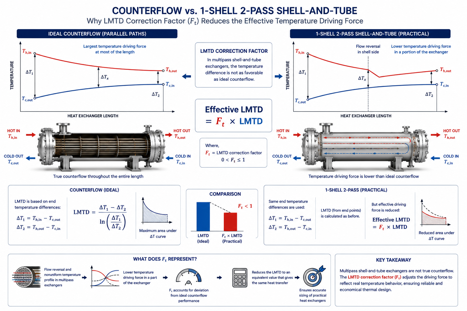
Real heat exchangers rarely operate under ideal counterflow conditions. The correction factor exists because practical exchanger flow arrangements behave differently from the textbook assumptions used in LMTD calculations.
Table of Contents
Why Isn’t LMTD Alone Enough?
LMTD works perfectly for ideal parallel-flow and counterflow heat exchangers. Industrial exchangers, however, are rarely that simple.
In the previous article, we discussed how the Log Mean Temperature Difference (LMTD) represents the average temperature driving force inside a heat exchanger.
For an ideal counterflow exchanger, the design equation is straightforward:
Heat Duty = U × A × LMTD
If every industrial heat exchanger behaved exactly like a perfect counterflow exchanger, the design process would almost end here.
Unfortunately, real process plants are much more complicated.
Most shell-and-tube heat exchangers are designed with:
- multiple tube passes
- one or more shell passes
- crossflow sections
- complex shell-side flow patterns
As soon as the flow pattern deviates from ideal counterflow, the actual temperature driving force becomes smaller than the ideal LMTD predicts.
If engineers ignored this difference, the exchanger would almost always be undersized.
This is why the Correction Factor (F) exists.
It adjusts the ideal LMTD so that the thermal calculation reflects how a real exchanger actually performs.
What Does the Correction Factor Actually Correct?
It corrects the temperature driving force—not the heat duty, not the heat transfer coefficient, and not the exchanger area.
One of the biggest misconceptions among young engineers is that the correction factor somehow improves the thermal calculation.
It does not.
The heat duty remains exactly the same.
The fluid properties remain the same.
The overall heat transfer coefficient (U) also remains unchanged.
The only thing that changes is the effective temperature difference available for heat transfer.
In practice, engineers use:
Effective LMTD = F × Ideal LMTD
The correction factor simply reduces the ideal LMTD to represent the actual flow arrangement.
Since F is always less than or equal to 1, the effective temperature driving force is always equal to or smaller than the ideal value.
Why Real Heat Exchangers Are Not Perfect Counterflow
Mechanical construction often determines the flow pattern long before thermal calculations begin.
Textbook diagrams usually show:
- one hot stream
- one cold stream
- perfectly opposite flow directions
Real shell-and-tube exchangers rarely look like that.
A typical exchanger may have:
- one shell pass
- two tube passes
- segmental baffles
- crossflow between baffles
- recirculation zones
The shell-side fluid continuously changes direction as it moves around the tube bundle.
Similarly, the tube-side fluid may reverse direction several times before leaving the exchanger.
As a result:
- temperature profiles become more complex
- local driving forces vary throughout the exchanger
- overall heat transfer becomes less efficient than ideal counterflow
The correction factor accounts for these differences.
Why Engineers Cannot Ignore the Correction Factor
Ignoring F usually results in an exchanger that is too small.
Imagine two exchangers with identical:
- heat duty
- overall heat transfer coefficient
- process temperatures
The first is a true counterflow exchanger.
The second is a one-shell, two-tube-pass exchanger.
If both are designed using the same LMTD without correction, both calculations would predict the same heat transfer area.
However, after installation, the second exchanger would transfer less heat because its actual temperature driving force is lower.
To compensate, it needs a larger heat transfer area.
That increase in area comes directly from applying the correction factor.
Why the Correction Factor Is Always Less Than One
Any deviation from ideal counterflow reduces the available temperature driving force.
Counterflow is considered the most thermally efficient flow arrangement because it maintains a relatively uniform temperature difference throughout the exchanger.
When engineers introduce:
- multiple passes
- crossflow
- shell-side mixing
- flow reversal
some of that efficiency is lost.
Therefore:
- Perfect counterflow → F = 1
- Practical shell-and-tube exchanger → F < 1
The greater the deviation from ideal counterflow, the lower the correction factor becomes.
What Determines the Value of F?
The correction factor depends on both exchanger geometry and process temperatures.
Many beginners think every one-shell-pass exchanger has the same correction factor.
It does not.
The value depends on several variables, including:
- shell pass arrangement
- tube pass arrangement
- inlet temperatures
- outlet temperatures
- temperature effectiveness
Two exchangers with identical mechanical construction can still have different correction factors because their operating temperatures differ.
That is why thermal design software calculates F individually for every case.
Why Designers Prefer Higher Correction Factors
A higher F usually means a more economical exchanger.
Suppose two designs have the same:
- heat duty
- overall heat transfer coefficient
One has:
F = 0.95
The other has:
F = 0.70
The second exchanger has a much lower effective LMTD.
To achieve the same heat duty, it requires:
- larger surface area
- more tubes
- bigger shell
- higher fabrication cost
Therefore, engineers generally prefer exchanger configurations that produce higher correction factors whenever practical.
Can Engineers Increase the Correction Factor?
Sometimes they can—but every improvement comes with trade-offs.
If the correction factor becomes too low, engineers may consider:
- changing the number of shell passes
- changing tube passes
- modifying flow arrangement
- selecting another exchanger type
These changes may improve thermal performance.
However, they may also increase:
- pressure drop
- fabrication complexity
- equipment cost
Like every aspect of exchanger design, optimizing F is a balancing exercise.
Why Thermal Design Software Still Shows the Correction Factor
Modern software calculates F automatically, but engineers still need to understand what it means.
Today’s thermal design programs calculate:
- LMTD
- correction factor
- effective temperature difference
within seconds.
This has led some engineers to ignore F completely.
Experienced designers do the opposite.
One of the first values they review is the correction factor.
It provides immediate insight into:
- whether the flow arrangement is efficient
- whether the exchanger is becoming unnecessarily large
- whether another configuration should be evaluated
The software performs the mathematics.
The engineer interprets the result.
When a Low Correction Factor Signals a Design Problem
A very low F often indicates that the selected flow arrangement should be reconsidered.
There is no single universal limit that applies to every exchanger.
However, in industrial practice, engineers become cautious when the correction factor becomes too low.
A low F generally indicates:
- poor utilization of temperature driving force
- larger exchanger size
- higher capital cost
- reduced design flexibility
Rather than immediately accepting the result, designers usually investigate whether another exchanger configuration can achieve a better thermal balance.
The Correction Factor Is Not a Safety Margin
It represents physics, not conservatism.
Another common misunderstanding is treating F like a design margin.
It is not.
A design margin intentionally adds extra capacity.
The correction factor simply reflects the actual thermal behaviour of the selected exchanger arrangement.
It does not make the exchanger safer.
It makes the calculation more realistic.
Why Plate Heat Exchangers Rarely Need an LMTD Correction
Many compact exchangers operate much closer to ideal counterflow.
Plate heat exchangers typically use true counterflow arrangements.
Their temperature profiles remain much closer to the ideal assumption used in LMTD calculations.
As a result:
- the correction factor is often close to 1
- temperature driving force is utilized more effectively
- smaller heat transfer areas become possible
This is one reason plate exchangers can be very compact for clean liquid services.
Correction Factor and Pressure Drop Must Be Balanced
Improving thermal performance should not create hydraulic problems.
Suppose an engineer changes the exchanger configuration to improve F.
The thermal calculation may improve.
However, the new configuration might also:
- increase shell-side pressure drop
- increase tube-side pressure drop
- require larger pumps
- increase operating cost
Thermal performance alone never determines the final design.
Hydraulic performance must also remain acceptable.
Common Misunderstandings About the Correction Factor
Most mistakes occur because engineers focus on the number instead of its purpose.
Some common misconceptions include:
“A lower F means poor exchanger quality.”
Not necessarily.
It simply reflects the chosen flow arrangement.
“The correction factor changes the heat duty.”
No.
Heat duty remains unchanged.
Only the effective temperature driving force changes.
“Software calculates F, so engineers don’t need to understand it.”
Software provides the value.
Engineers decide whether that value represents a practical exchanger.
“A correction factor of 1 should always be the goal.”
Not always.
Achieving F close to 1 may require:
- more complex equipment
- higher pressure drop
- greater capital cost
Engineering is about optimization—not maximizing a single parameter.
Operator Perspective
Operators rarely know the correction factor, but they experience its consequences every day.
A poorly selected flow arrangement may appear as:
- insufficient cooling
- inability to reach design temperatures
- higher utility consumption
- reduced production during peak loads
These problems often originate during thermal design, long before the exchanger reaches the plant.
Owner Perspective
Using the correction factor correctly helps balance capital cost and long-term performance.
For plant owners, proper application of the correction factor helps achieve:
- realistic exchanger sizing
- lower risk of undersized equipment
- better energy efficiency
- improved operational flexibility
- optimized lifecycle cost
Ignoring it may reduce purchase cost initially but increase operating problems throughout the exchanger’s life.
Final Perspective
The correction factor exists because industrial heat exchangers do not behave like ideal counterflow exchangers.
Multiple passes, shell-side flow patterns, and practical construction reduce the available temperature driving force.
Rather than ignoring these realities, engineers adjust the ideal LMTD using the correction factor to represent actual exchanger performance.
The correction factor is therefore not a mathematical complication added to the design process.
It is the link between textbook heat transfer theory and the way real heat exchangers operate in industrial plants.
Explore the complete series in the Heat Exchanger Engineering Hub.

A practicing chemical engineer with 17+ years of experience in process design, project execution, commissioning, and plant operations. Focused on practical engineering judgment beyond textbook explanations.