
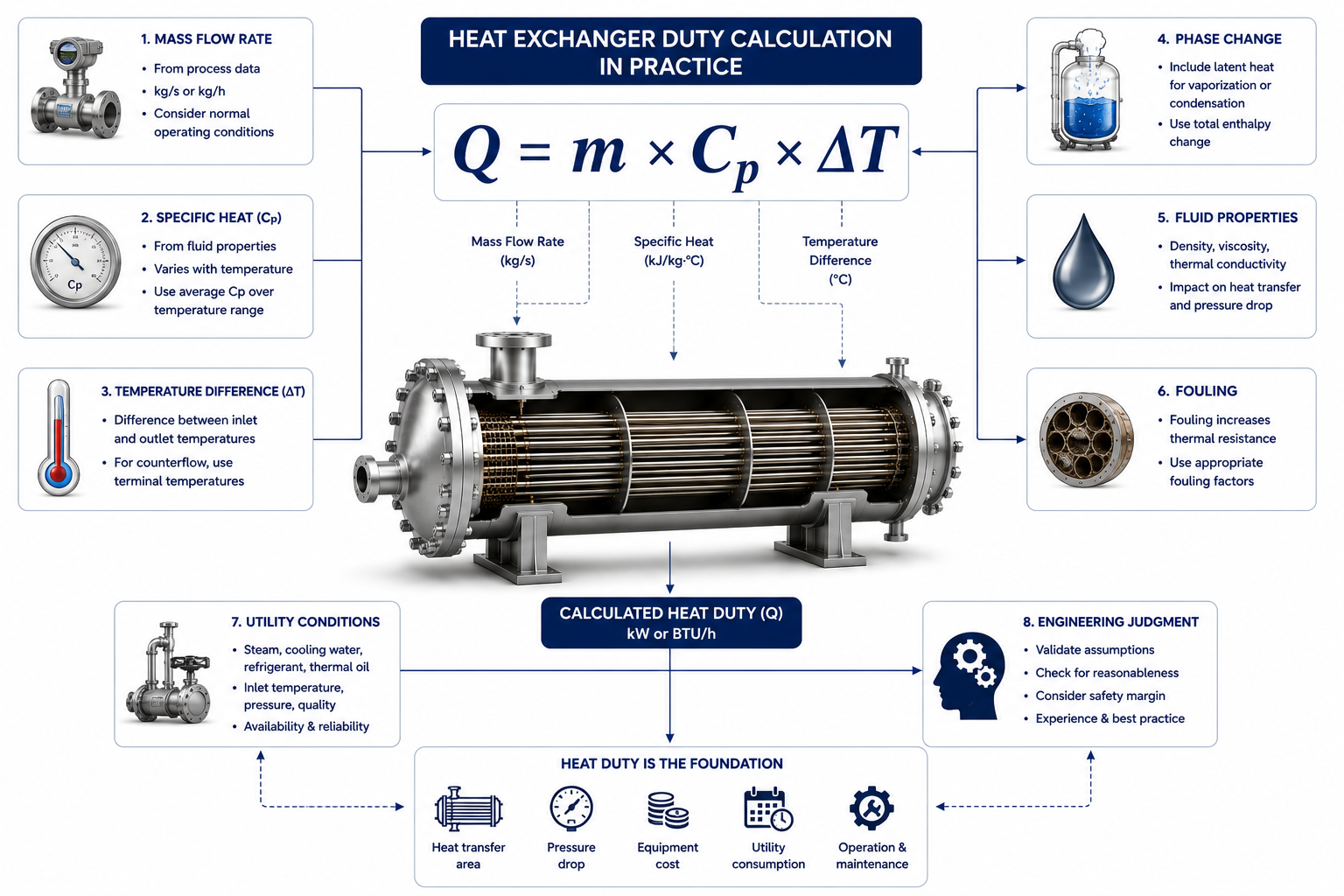
Every Heat Duty Calculation Begins with Equations but Ends with Engineering Judgment
One of the first calculations every process engineer learns is the heat exchanger duty equation:
Q = m × Cp × ΔT
At first glance, it appears remarkably simple.
Determine the:
- flow rate
- specific heat
- temperature change
Multiply them together, and the required heat duty is known.
Many engineering textbooks present the calculation this way, making heat exchanger design seem straightforward.
Real industrial projects are rarely that simple.
Experienced engineers know that the equation itself is usually the easiest part of the calculation.
The real challenge lies in answering questions such as:
- Which flow rate should be used—normal, design, or maximum?
- Can the specific heat be treated as constant?
- What happens if the process fluid changes phase?
- Which operating case should govern the design?
- Should future operating flexibility be considered?
In practice, heat duty calculations are built upon numerous assumptions.
Some assumptions are reasonable.
Others can cause oversized exchangers, undersized exchangers, excessive utility consumption, or long-term operating problems.
This article explains how engineers calculate heat exchanger duty in real projects and the practical assumptions that influence every thermal design.
Table of Contents
Heat Duty Represents Energy Transfer
Before Designing an Exchanger, Engineers Must Know How Much Heat Must Move
A heat exchanger does not create heat.
It simply transfers thermal energy from one fluid to another.
The heat duty represents the amount of energy that must be transferred every hour or every second to achieve the required process conditions.
Typical duties include:
- cooling a reactor product
- heating a feed stream
- condensing process vapor
- vaporizing liquid
- recovering waste heat
Until the heat duty is established, the exchanger cannot be sized.
Everything else depends on this first calculation.
The Basic Equation Is Only the Starting Point
The Mathematics Is Simple—Selecting the Correct Values Is Not
For sensible heating or cooling, engineers commonly use:
Q = m × Cp × ΔT
Where:
- Q = Heat duty
- m = Mass flow rate
- Cp = Specific heat capacity
- ΔT = Temperature change
The equation is straightforward.
The engineering decisions behind each variable are much more complicated.
Which Flow Rate Should Be Used?
Design Flow Is Not Always Normal Flow
Every process has multiple operating conditions.
Examples include:
- normal operation
- maximum production
- turndown operation
- startup
- future expansion
Young engineers sometimes use whichever flow rate is easiest to obtain.
Experienced engineers first determine:
Which operating case governs the exchanger design?
Designing only for today’s normal production may create problems if the plant later increases throughput.
Conversely, designing for unrealistic maximum flow can produce unnecessary capital cost.
Selecting the correct design basis is one of the first practical assumptions.
Specific Heat Is Rarely Constant
Fluid Properties Change with Temperature
Many textbook examples assume that specific heat remains constant.
Industrial fluids rarely behave that way.
As temperature changes:
- specific heat changes
- density changes
- viscosity changes
- thermal conductivity changes
For narrow temperature ranges, assuming constant Cp may be reasonable.
For wider temperature ranges or complex hydrocarbon mixtures, engineers often use average values or property data generated from process simulation software.
Ignoring property variation may introduce noticeable errors into duty calculations.
Temperature Difference Is Not Always Obvious
Which Temperature Should Be Used?
Suppose a process stream enters at:
150°C
and leaves at:
90°C
The temperature difference appears to be:
60°C.
Simple enough.
However, engineers must first confirm:
- Are these guaranteed temperatures?
- Are they operating temperatures or design temperatures?
- Do seasonal utility changes affect them?
- Are these temperatures achievable under all operating conditions?
Using unrealistic temperatures produces unrealistic heat duties.
Phase Change Requires a Different Approach
Sensible Heat and Latent Heat Are Not the Same
The equation Q = m × Cp × ΔT applies only when the fluid remains in the same phase.
If condensation or boiling occurs, latent heat must also be considered.
Examples include:
- steam condensation
- hydrocarbon condensation
- refrigerant evaporation
- reboiler operation
In these cases, heat duty depends primarily on:
- latent heat of vaporization
- vapor quality
- operating pressure
Applying the sensible heat equation to phase-change services is a common beginner’s mistake.
Average Fluid Properties Are Practical Approximations
Engineers Balance Accuracy and Practicality
Industrial property data changes continuously with temperature.
Using exact properties at every point along the exchanger would require complex calculations.
Instead, designers often use:
- average Cp
- average density
- average viscosity
These assumptions simplify calculations while maintaining acceptable engineering accuracy.
The objective is not perfect mathematical precision.
It is a realistic design.
Heat Losses Are Often Ignored Initially
Early Calculations Usually Assume Perfect Heat Transfer
During preliminary design, engineers commonly assume:
Heat lost by one stream equals heat gained by the other.
Small environmental heat losses are often neglected.
This assumption is generally reasonable because exchanger heat losses to the surroundings are relatively small compared with the total process duty.
However, for:
- cryogenic equipment
- very high-temperature systems
- long transfer lines
external heat losses may require separate evaluation.
Utility Conditions Are Assumed to Be Stable
Reality Is More Variable
Cooling water may enter at:
30°C
during winter but reach:
36°C
during summer.
Steam pressure may fluctuate.
Air cooler performance changes with ambient temperature.
Despite these realities, thermal calculations usually begin with standard utility conditions.
Engineers then evaluate whether the exchanger can tolerate expected operating variations.
Fouling Is Usually Not Present on Day One
Clean Performance Is Only the Starting Point
Thermal design begins with clean heat transfer surfaces.
This allows engineers to establish the basic exchanger size.
Only afterward is fouling incorporated into the design.
The assumption of clean performance is therefore temporary—not permanent.
The exchanger must ultimately perform acceptably after fouling develops.
Heat Duty Should Be Verified by Energy Balance
Independent Verification Reduces Errors
Experienced engineers rarely rely on a single calculation.
Whenever possible, they verify duty using:
- process simulation
- equipment energy balance
- reactor calculations
- utility consumption
- upstream and downstream process data
If two independent methods produce similar duties, confidence in the design increases.
Process Simulation Is Helpful—Not Infallible
Simulation Depends on Input Quality
Modern projects frequently obtain heat duty from process simulation software.
Programs provide:
- fluid properties
- enthalpy values
- phase behavior
- heat duty
These results are extremely useful.
However, simulation accuracy depends entirely on:
- process model quality
- thermodynamic package
- operating assumptions
Engineers still review the results before accepting them.
Simulation supports engineering judgment—it does not replace it.
Future Plant Operation Should Be Considered
Today’s Duty May Not Be Tomorrow’s Duty
Many plants increase production after commissioning.
If future expansion is expected, engineers may include reasonable flexibility within the design basis.
This does not mean designing for every possible future condition.
It means avoiding a design that becomes a bottleneck shortly after startup.
Small Errors Can Produce Large Equipment Changes
Duty Calculation Influences Everything
An error of only a few percent in heat duty may affect:
- exchanger area
- shell diameter
- tube count
- utility consumption
- project cost
Because every later calculation depends on duty, the first calculation deserves careful review.
Practical Assumptions Experienced Engineers Make
Not Every Assumption Is a Shortcut
Experienced designers commonly make assumptions such as:
- using average fluid properties over moderate temperature ranges
- selecting the governing operating case instead of every possible case
- neglecting minor external heat losses during preliminary design
- validating duty using independent calculations
- considering realistic utility conditions rather than ideal ones
These assumptions simplify engineering without compromising design quality.
Common Mistakes in Duty Calculations
Most Errors Are Not Mathematical
Typical mistakes include:
- using volumetric flow instead of mass flow without proper conversion
- assuming constant fluid properties over large temperature ranges
- ignoring latent heat during phase change
- selecting incorrect design flow rate
- confusing operating temperatures with design temperatures
- failing to verify calculations independently
Most thermal design problems begin with incorrect assumptions rather than incorrect equations.
Operator Perspective
Operators rarely calculate heat duty.
However, they immediately notice when the original calculation was based on unrealistic assumptions.
The consequences appear as:
- inadequate cooling
- excessive steam consumption
- inability to achieve target temperatures
- reduced production
Many operating challenges can be traced back to the original design basis.
Owner Perspective
For plant owners, accurate heat duty calculations help achieve:
- correctly sized exchangers
- lower capital cost
- reduced utility consumption
- improved process reliability
- easier future plant expansion
A few hours spent validating the design basis often prevents years of operating inefficiency.
How This Article Fits into the Thermal Design Series
This article introduced the first step of practical thermal design:
calculating the required heat duty using realistic engineering assumptions.
The following support articles will explain:
- why LMTD is an application tool rather than a classroom equation,
- why correction factors exist,
- how engineers actually use overall heat transfer coefficient (U),
- why operating plants rarely match thermal calculations,
- and how experienced designers build practical margins into exchanger design.
Together, these topics explain how thermal design progresses from process data to a reliable industrial heat exchanger.
Final Perspective
Calculating heat exchanger duty is not simply a matter of applying Q = m × Cp × ΔT.
The equation is only the framework.
The real engineering lies in selecting realistic values for:
- flow rate,
- fluid properties,
- operating temperatures,
- phase behavior,
- and design conditions.
Every duty calculation contains assumptions.
The quality of those assumptions largely determines the quality of the final heat exchanger.
Successful thermal design begins not with complicated equations, but with sound engineering judgment about the process the exchanger is expected to serve.
Explore the complete series in the Heat Exchanger Engineering Hub.

A practicing chemical engineer with 17+ years of experience in process design, project execution, commissioning, and plant operations. Focused on practical engineering judgment beyond textbook explanations.