
Heat Always Needs a Driving Force
Heat naturally flows from a higher temperature to a lower temperature.
Without a temperature difference:
- no heat transfer occurs
- no exchanger is required
The larger the temperature difference,
the easier it becomes to transfer heat.
The smaller the temperature difference,
the larger the exchanger usually becomes.
This simple physical principle explains why temperature difference is often called the driving force for heat transfer.
Table of Contents
Why a Single Temperature Difference Cannot Represent an Entire Exchanger
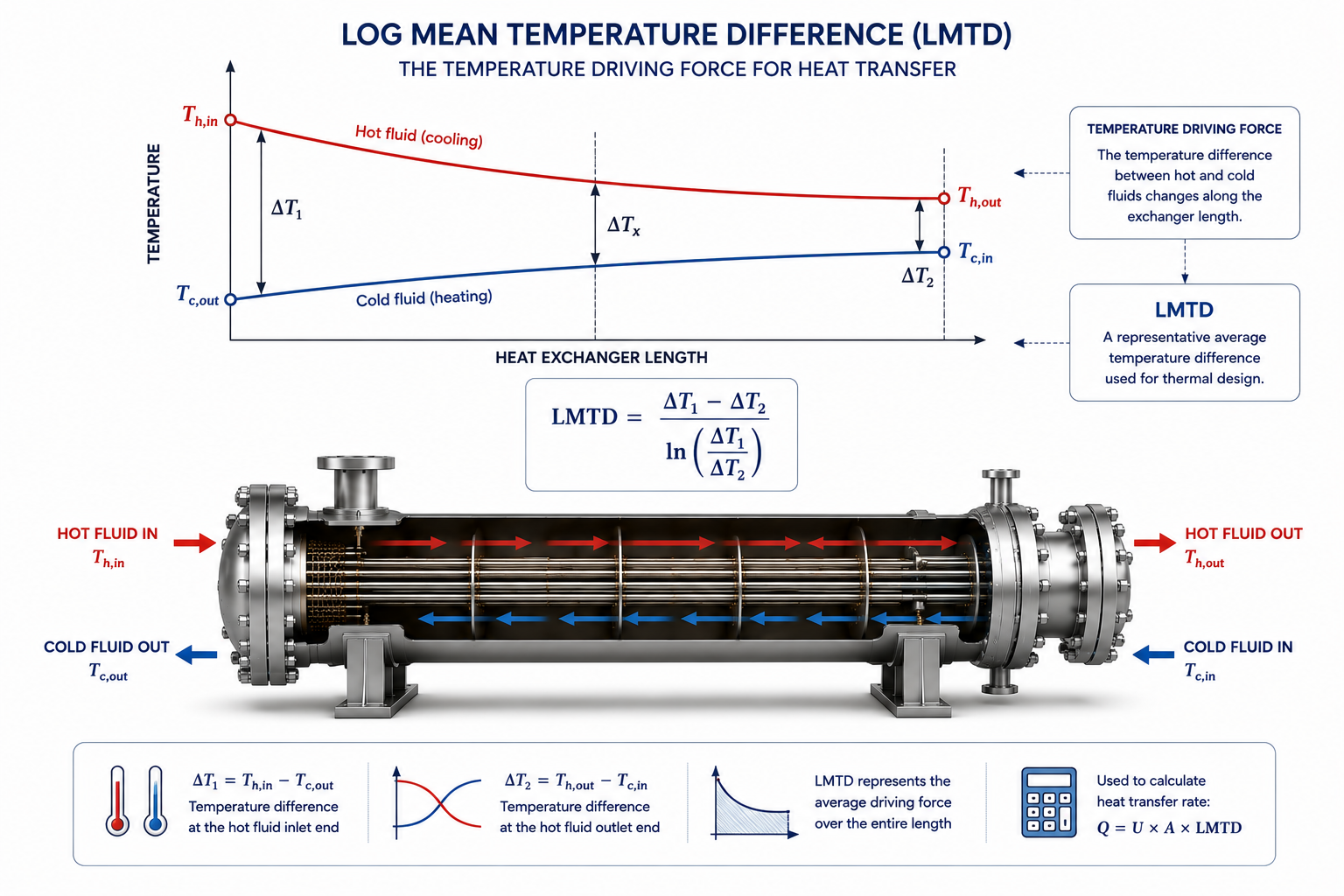
Temperatures Continuously Change Along the Length
Many beginners assume the temperature difference remains constant throughout the exchanger.
It does not.
Consider a simple cooler.
At the inlet:
- the hot fluid is at its highest temperature
- the cooling fluid is at its lowest temperature
The temperature difference is therefore large.
As both fluids move through the exchanger:
- the hot stream cools
- the cold stream warms
The temperature difference gradually decreases.
At the outlet, the driving force is much smaller.
Since the temperature difference changes continuously, engineers cannot use only the inlet or outlet value.
A representative average is required.
That representative value is the Log Mean Temperature Difference (LMTD).
Why Engineers Use LMTD Instead of an Arithmetic Average
Heat Transfer Does Not Change Linearly
A common question is:
Why not simply average the inlet and outlet temperature differences?
Because heat transfer is not linear.
The relationship between heat transfer and temperature difference changes throughout the exchanger.
An arithmetic average would overestimate or underestimate the true driving force depending on the temperature profile.
LMTD accounts for the actual variation in driving force across the exchanger.
It provides a more realistic basis for sizing heat transfer area.
LMTD Connects Thermal Duty with Exchanger Size
This Is Where Design Begins
Once engineers know:
- required heat duty
- estimated overall heat transfer coefficient
- available temperature driving force
they can estimate the required heat transfer area.
The relationship is:
Heat Duty = U × Area × LMTD
This equation reveals something important.
If:
- heat duty remains constant
- U remains unchanged
then:
a smaller LMTD requires a larger exchanger.
This is one of the most important concepts in heat exchanger design.
Small LMTD Means Large Equipment
Close Temperature Approaches Are Expensive
Suppose two designs require exactly the same heat duty.
One has a large temperature driving force.
The other has only a small temperature difference between the two fluids.
The second exchanger must compensate by increasing heat transfer area.
This generally means:
- larger shell diameter
- more tubes
- longer tube length
- higher equipment cost
Engineers therefore try to preserve as much temperature driving force as practical.
Why Process Engineers Worry About Approach Temperature
Every Degree Matters
The approach temperature is the smallest temperature difference between the hot and cold streams.
Many young engineers focus only on outlet temperatures.
Experienced engineers pay close attention to the approach temperature because it directly affects exchanger size.
For example:
Reducing the approach from:
15°C
to
5°C
may appear insignificant.
However, it can dramatically increase the required heat transfer area.
Sometimes doubling it.
That additional area increases:
- fabrication cost
- equipment weight
- plot space
- maintenance effort
Achieving a very close temperature approach is rarely free.
Counterflow Makes Better Use of LMTD
Flow Arrangement Influences the Driving Force
Imagine two exchangers with identical duties.
The only difference is the flow arrangement.
One operates in:
- parallel flow
The other operates in:
- counterflow
Counterflow usually maintains a more uniform temperature difference throughout the exchanger.
As a result:
- LMTD increases
- required area decreases
- thermal efficiency improves
This is why counterflow is preferred whenever practical.
The advantage comes not from better materials or larger equipment, but from better utilization of the available temperature difference.
LMTD Does Not Work Alone
Other Parameters Matter Too
Some engineers mistakenly assume that increasing LMTD automatically creates the best design.
It does not.
Thermal design also depends on:
- heat transfer coefficient
- pressure drop
- fouling
- flow arrangement
- mechanical limitations
LMTD is one part of a larger design process.
It should never be evaluated in isolation.
LMTD Assumes Stable Operating Conditions
Real Plants Are More Dynamic
Traditional LMTD calculations assume:
- steady flow
- constant temperatures
- stable operating conditions
Actual plants experience:
- production changes
- seasonal utility variation
- feed composition changes
- startup
- shutdown
Consequently, the actual driving force changes throughout plant operation.
Engineers therefore design exchangers to perform acceptably over an operating range rather than at only one operating point.
LMTD Alone Cannot Handle Every Flow Arrangement
Real Exchangers Are Often More Complex
Many industrial exchangers do not operate in ideal counterflow or parallel flow.
Examples include:
- one-shell two-pass exchangers
- multi-pass shell-and-tube exchangers
- crossflow exchangers
In these situations, the actual temperature profile differs from the ideal LMTD assumption.
This is why engineers apply an LMTD correction factor, often called the F-factor.
The correction factor adjusts the ideal LMTD to represent the actual exchanger configuration.
The next article in this series explains why this correction becomes necessary.
LMTD Is One of the First Feasibility Checks
Experienced Engineers Look at It Early
Before performing detailed thermal design, experienced engineers often estimate LMTD.
A very small LMTD immediately suggests:
- large exchanger area
- higher capital cost
- possible space limitations
Conversely, a healthy driving force often indicates that the exchanger can be designed economically.
LMTD therefore serves as an early design indicator—not merely a final calculation.
Why Software Does Not Eliminate the Need to Understand LMTD
Thermal Programs Calculate It Automatically
Modern thermal design software instantly calculates:
- LMTD
- correction factors
- heat transfer coefficients
- pressure drop
This automation sometimes leads young engineers to believe they no longer need to understand LMTD.
The opposite is true.
Software provides numbers.
Engineers must determine whether those numbers are reasonable.
For example:
A calculated LMTD of only a few degrees should immediately raise questions about:
- exchanger size
- operating feasibility
- economic viability
Understanding the significance of the result is far more valuable than performing the calculation manually.
Common Misunderstandings About LMTD
Mistake 1 – Treating It as Just Another Formula
LMTD is not merely an equation.
It represents the average thermal driving force available inside the exchanger.
Mistake 2 – Assuming Higher LMTD Is Always Better
A larger LMTD usually reduces exchanger size.
However, increasing LMTD may require:
- higher utility consumption
- different operating conditions
- additional process changes
The objective is optimization—not simply maximizing LMTD.
Mistake 3 – Ignoring Temperature Profiles
Some engineers focus only on inlet and outlet temperatures.
Experienced designers examine how temperatures change throughout the exchanger.
The temperature profile often explains whether a proposed design is practical.
Operator Perspective
Operators rarely calculate LMTD.
Yet they experience its effects daily.
If the original design provides insufficient temperature driving force, they may observe:
- poor cooling during summer
- inability to reach target temperatures
- increasing utility demand
- reduced production rates
Many operating limitations originate from inadequate thermal driving force rather than poor operation.
Owner Perspective
For plant owners, proper use of LMTD helps achieve:
- economical exchanger sizing
- lower capital investment
- improved energy recovery
- reduced utility consumption
- better long-term plant performance
Understanding temperature driving force early in the project often prevents expensive redesign later.
Final Perspective
LMTD is often taught as a mathematical calculation.
In industry, it serves a much larger purpose.
It tells engineers whether the available temperature difference is sufficient to transfer the required heat economically.
It influences:
- exchanger size,
- equipment cost,
- operating flexibility,
- and long-term thermal performance.
The equation itself is simple.
Understanding what the result means—and how it affects the entire exchanger design—is what separates practical heat exchanger design from classroom calculations.
Explore the complete series in the Heat Exchanger Engineering Hub.

A practicing chemical engineer with 17+ years of experience in process design, project execution, commissioning, and plant operations. Focused on practical engineering judgment beyond textbook explanations.