
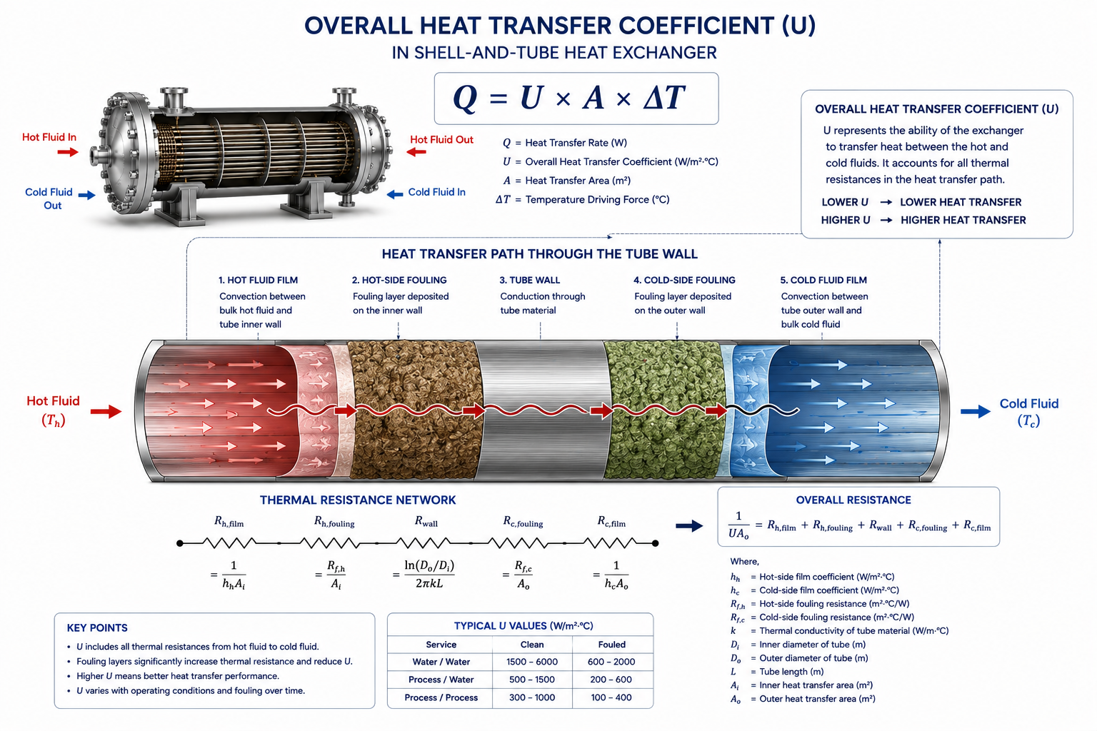
The Overall Heat Transfer Coefficient (U) is one of the most important parameters in heat exchanger design, yet experienced engineers rarely treat it as a fixed value from a handbook. In real projects, U is an outcome of the design process—not simply a number selected from a table.
Table of Contents
Why U Is Often Misunderstood
Most textbooks introduce U as a property. In industrial practice, it is treated as a design target that evolves throughout the thermal calculation.
Every process engineer eventually encounters the familiar heat exchanger equation:
Q = U × A × ΔT
The equation appears simple.
If the:
- heat duty (Q),
- temperature driving force (ΔT),
- and overall heat transfer coefficient (U)
are known, the required heat transfer area (A) can be calculated.
Because textbooks usually provide tables of “typical U values,” many young engineers develop a habit of selecting a value directly from those tables and moving on with the calculation.
That approach may work for classroom exercises.
It rarely works in engineering design.
In an industrial project, engineers do not simply ask:
“What is the U value?”
Instead, they ask:
- Is this U realistic for the process fluids?
- Can it be achieved without excessive pressure drop?
- Will fouling reduce it significantly?
- How will it change over the exchanger’s operating life?
These questions shift the focus away from the number itself and toward the engineering decisions that influence it.
What Does U Actually Represent?
The overall heat transfer coefficient represents the combined resistance to heat flow through the entire exchanger—not just one fluid.
Heat must pass through several layers before it reaches the other process stream.
It typically moves through:
- the hot-side fluid film
- deposits on the hot surface
- the tube wall
- deposits on the cold surface
- the cold-side fluid film
Each layer resists heat flow.
The overall heat transfer coefficient combines all these resistances into a single value that describes how easily heat moves from one fluid to the other.
A high U means heat moves relatively easily.
A low U means the exchanger faces greater resistance.
Although U is expressed as one number, it represents the combined behaviour of the entire heat transfer path.
Engineers Rarely Start with the Final U Value
The first U used in thermal design is usually an estimate—not the final design value.
When thermal design begins, engineers often have only:
- process conditions
- fluid properties
- expected fouling
- preliminary exchanger configuration
At this stage, the actual U is unknown.
Therefore, designers begin with an estimated value based on:
- previous projects
- company design standards
- similar process services
- vendor experience
Using this estimated U allows an initial exchanger size to be calculated.
The design is then refined repeatedly until the calculated U and exchanger geometry become consistent.
In other words, U evolves during the design process.
Why Textbook U Values Can Be Misleading
Reference tables provide a starting point—not a guaranteed design value.
Most heat transfer books contain tables such as:
- water to water
- steam to water
- oil to water
- gas to gas
along with typical ranges of overall heat transfer coefficients.
These tables are useful for preliminary estimation.
However, they assume conditions that may not match your plant.
For example, actual U depends on:
- fluid velocity
- viscosity
- fouling tendency
- exchanger geometry
- tube material
- operating temperature
- flow arrangement
Changing any one of these variables can significantly alter the achievable U.
That is why experienced engineers never treat handbook values as fixed design data.
U Is Strongly Influenced by Fluid Velocity
Increasing velocity usually improves heat transfer—but not without consequences.
One of the simplest ways to increase U is to increase fluid velocity.
Higher velocity generally:
- reduces boundary layer thickness
- increases turbulence
- improves convection
As a result, the film resistance decreases and U increases.
However, higher velocity also increases:
- pressure drop
- pumping power
- erosion risk
- operating cost
Thermal designers therefore seek an acceptable balance rather than simply maximizing U.
The Lowest Film Coefficient Usually Controls U
Improving the strongest side has little value if the weakest side remains unchanged.
Consider an exchanger where:
- steam condenses on one side
- heavy oil flows on the other
Steam condensation provides an extremely high heat transfer coefficient.
Heavy oil, because of its viscosity, produces a much lower coefficient.
The overall heat transfer coefficient becomes dominated by the heavy oil side.
Improving the steam side further produces very little improvement.
Experienced engineers first identify the largest thermal resistance before attempting to improve U.
Fouling Changes U Throughout the Exchanger’s Life
The U value used during design is not the same as the U observed after years of operation.
Every exchanger gradually accumulates:
- scale
- corrosion products
- biological growth
- polymer deposits
- suspended solids
These deposits increase thermal resistance.
As fouling grows:
- U decreases
- heat transfer declines
- outlet temperatures drift
- utility consumption rises
For this reason, engineers design around a dirty U, not simply the clean U measured immediately after commissioning.
Mechanical Decisions Influence U
Thermal performance depends on more than process conditions.
Several mechanical design choices affect the achievable U, including:
- tube diameter
- tube layout
- tube pitch
- baffle spacing
- tube length
- shell diameter
Changing these parameters changes:
- flow distribution
- turbulence
- heat transfer
- pressure drop
Consequently, U is closely linked with the mechanical configuration of the exchanger.
Process Fluids Behave Differently
Two exchangers with identical duties may have completely different U values.
Consider three services:
- cooling water
- light hydrocarbon
- heavy fuel oil
Each fluid behaves differently because of differences in:
- viscosity
- thermal conductivity
- specific heat
- flow characteristics
Even if all three exchangers perform the same heat duty, their achievable U values will differ.
This explains why experienced engineers avoid asking:
“What is the correct U?”
Instead, they ask:
“What U is realistic for this service?”
Software Calculates U—Engineers Validate It
Thermal software performs the calculations, but engineering judgment determines whether the result is realistic.
Modern thermal design software calculates:
- film coefficients
- fouling resistance
- overall U
- pressure drop
automatically.
However, software cannot determine whether:
- process data are realistic
- fouling assumptions are reasonable
- velocities are acceptable
- maintenance philosophy has been considered
If the calculated U appears unusually high or unusually low, experienced engineers investigate the reason rather than accepting the number without question.
A Higher U Is Not Always the Best Design
Pursuing the highest possible U can create unnecessary operating problems.
Many young engineers believe that increasing U automatically improves the exchanger.
In reality, increasing U may require:
- higher fluid velocity
- smaller hydraulic passages
- increased pressure drop
- larger pumps
- higher operating costs
The objective is not the maximum U.
It is the optimum combination of:
- thermal performance
- pressure drop
- reliability
- maintenance
- lifecycle cost
Why Designers Sometimes Accept a Lower U
A slightly larger exchanger may be more economical over its operating life.
Suppose an engineer has two options.
Option A:
- high U
- compact exchanger
- high pressure drop
Option B:
- lower U
- larger exchanger
- lower pumping cost
- easier maintenance
Although Option B requires more heat transfer area, it may reduce operating expenses for decades.
This illustrates why exchanger design is always an optimization exercise rather than a search for the highest U.
U Changes as the Plant Ages
The value calculated during design gradually changes throughout the exchanger’s service life.
Plant operation is never perfectly steady.
Over time:
- fouling increases
- flow rates change
- utilities fluctuate
- process fluids vary
Consequently, the effective U also changes.
Engineers therefore include realistic fouling allowances and operating margins so that acceptable performance continues even after the exchanger no longer operates under clean conditions.
Common Misunderstandings About U
Many design mistakes arise from misunderstanding what U actually represents.
“U Is a Material Property”
No.
Unlike thermal conductivity, U is not a material property.
It depends on the complete exchanger system.
“Higher U Always Means Better Design”
Not necessarily.
A very high U achieved through excessive velocity may create unacceptable pressure drop and erosion.
“Handbook Values Can Be Used Directly”
Reference tables provide useful starting estimates.
Final U values should always be validated through detailed thermal calculations.
“U Never Changes”
In reality, U changes throughout the exchanger’s operating life because operating conditions and fouling change continuously.
Operator Perspective
Operators may never calculate U, but they work with its consequences every day.
As U gradually decreases due to fouling, operators often observe:
- reduced cooling capacity
- higher steam consumption
- increasing outlet temperatures
- reduced production rates
Many operating problems are actually symptoms of a declining overall heat transfer coefficient.
Owner Perspective
A realistic U value leads to a more reliable and economical heat exchanger.
For plant owners, proper estimation of U helps achieve:
- correct exchanger sizing
- lower lifecycle cost
- predictable maintenance intervals
- reduced utility consumption
- improved long-term reliability
Using an unrealistic U may reduce the purchase price initially but create operational challenges throughout the equipment’s life.
Final Perspective
The overall heat transfer coefficient is not a number copied from a handbook.
It is the result of countless engineering decisions involving:
- process conditions,
- fluid properties,
- exchanger geometry,
- fouling behaviour,
- pressure drop,
- and maintenance philosophy.
Textbook U values provide useful starting points.
Successful heat exchanger design comes from understanding how U develops, how it changes over time, and how it influences the balance between thermal performance, operating cost, and long-term reliability.
That is how experienced engineers use U—not as a fixed input, but as a practical indicator of whether the proposed exchanger is likely to succeed in real plant operation.
Explore the complete series in the Heat Exchanger Engineering Hub.

A practicing chemical engineer with 17+ years of experience in process design, project execution, commissioning, and plant operations. Focused on practical engineering judgment beyond textbook explanations.