
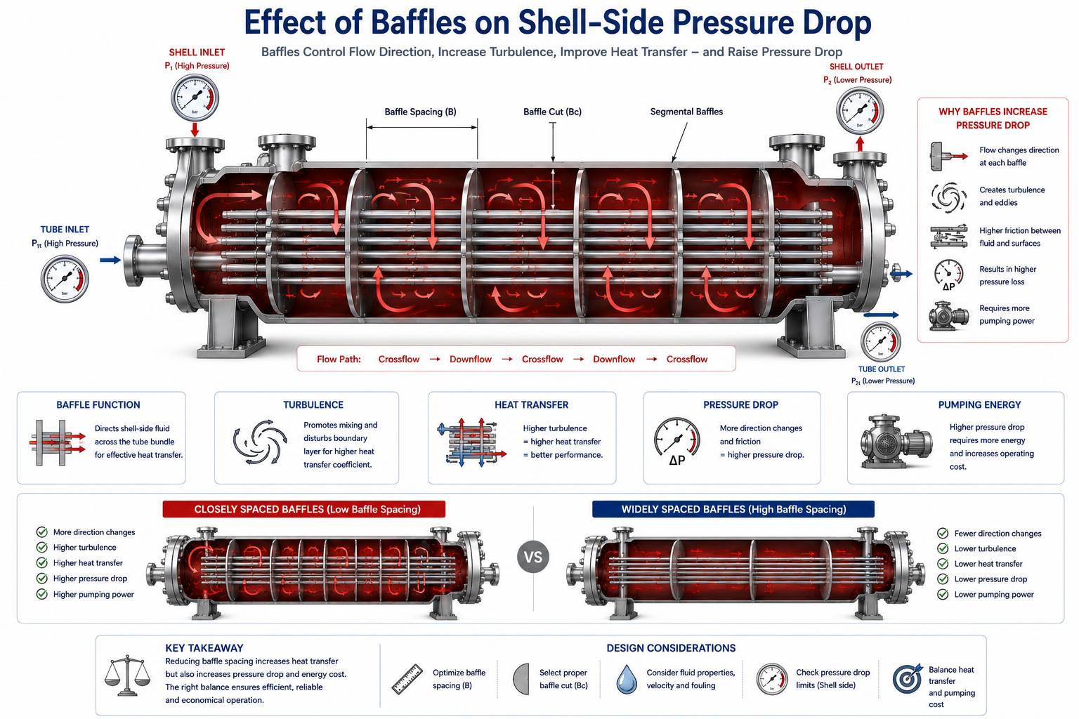
Baffles are among the most important internal components of a shell-and-tube heat exchanger. They improve shell-side heat transfer by directing fluid across the tube bundle, but they also create additional flow resistance. Every baffle added to improve thermal performance increases pressure drop, making baffle design one of the most important optimization decisions in heat exchanger engineering.
Unlike the tube side, where fluid follows a relatively predictable path through the tubes, shell-side flow is far more complex.
Without any internal guidance, the shell-side fluid would naturally take the path of least resistance, flowing along the shell wall and bypassing much of the tube bundle. Heat transfer would be poor because large portions of the heat transfer surface would receive very little effective flow.
Baffles solve this problem.
They repeatedly redirect the shell-side fluid across the tubes, increasing turbulence, improving fluid distribution, and making much better use of the available heat transfer area.
However, this improvement comes at a cost.
Every change in flow direction creates friction and energy loss. As the shell-side fluid moves through successive baffle windows and across the tube bundle, the pressure drop increases.
This is why experienced engineers never ask, “How many baffles should we use?” Instead, they ask, “What baffle arrangement provides the best balance between heat transfer and allowable pressure drop?”
Understanding this balance is fundamental to successful shell-and-tube heat exchanger design.
Table of Contents
Why Shell-and-Tube Heat Exchangers Need Baffles
Without baffles, much of the shell-side fluid would bypass the tube bundle instead of transferring heat efficiently.
The shell inside a heat exchanger is much larger than the spaces between individual tubes.
If shell-side fluid were allowed to flow freely, it would naturally seek the easiest path.
This would result in:
- poor contact with the tubes,
- low turbulence,
- reduced heat transfer,
- uneven temperature distribution.
Baffles force the fluid to move across the tube bundle instead of around it.
By repeatedly changing the flow direction, they increase the interaction between the process fluid and the heat transfer surface.
The result is significantly improved thermal performance.
How Baffles Increase Shell-Side Pressure Drop
Every change in flow direction creates additional hydraulic resistance.
As shell-side fluid encounters a baffle, it cannot continue moving in a straight line.
Instead, it must:
- change direction,
- pass through the baffle window,
- flow across the tube bundle,
- repeat the process at the next baffle.
Each redirection creates:
- friction losses,
- local turbulence,
- flow separation,
- energy dissipation.
Individually, these losses may appear small.
Across dozens of baffles, however, they combine to produce a significant shell-side pressure drop.
This explains why shell-side hydraulics are generally more complex than tube-side hydraulics.
Baffles Improve Heat Transfer by Increasing Turbulence
The same turbulence that improves heat transfer also increases pressure loss.
One of the primary purposes of baffles is to increase shell-side velocity across the tubes.
Higher velocity reduces the thickness of the thermal boundary layer and improves the shell-side heat transfer coefficient.
As turbulence increases:
- heat transfer improves,
- the overall heat transfer coefficient (U) increases,
- required heat transfer area may decrease.
However, greater turbulence also means greater friction.
Consequently:
- shell-side pressure drop increases,
- pumping requirements become higher.
This is one of the fundamental trade-offs in heat exchanger design.
Baffle Spacing Has a Major Influence on Pressure Drop
Closer baffles improve heat transfer but increase hydraulic resistance.
One of the most important design decisions is selecting the spacing between adjacent baffles.
When baffles are placed closer together:
- shell-side flow changes direction more frequently,
- crossflow velocity increases,
- turbulence increases,
- heat transfer improves.
At the same time:
- pressure drop increases,
- pumping power rises,
- operating cost becomes higher.
If the spacing is increased:
- hydraulic resistance decreases,
- pressure drop falls,
- shell-side velocity decreases,
- heat transfer performance may decline.
Neither extreme is desirable.
The objective is to identify the spacing that provides the best overall performance.
Baffle Cut Also Affects Hydraulic Performance
The size of the baffle opening determines how much fluid crosses the tube bundle and how much passes through the window section.
A baffle does not completely block shell-side flow.
Part of the baffle is removed to create an opening known as the baffle cut.
This opening allows fluid to move from one section of the shell to the next.
Changing the baffle cut alters:
- flow distribution,
- shell-side velocity,
- pressure drop,
- heat transfer effectiveness.
A smaller baffle cut generally forces more fluid across the tube bundle, increasing heat transfer but also increasing pressure drop.
A larger cut reduces hydraulic resistance but may allow excessive bypass flow, reducing thermal efficiency.
Too Many Baffles Can Become a Hydraulic Problem
More baffles do not always produce a better heat exchanger.
A common misconception is that increasing the number of baffles will continuously improve exchanger performance.
Initially, additional baffles increase turbulence and improve heat transfer.
Beyond a certain point, however:
- pressure drop rises rapidly,
- pumping power increases,
- operating cost grows,
- only modest thermal improvement is achieved.
The exchanger becomes hydraulically inefficient.
Good design seeks the point where additional baffles no longer justify the extra pressure loss.
Too Few Baffles Reduce Thermal Performance
Minimizing pressure drop can also reduce exchanger effectiveness.
Removing baffles or increasing their spacing reduces shell-side resistance.
However, it also allows:
- greater bypass flow,
- lower turbulence,
- uneven velocity distribution,
- poorer use of the heat transfer surface.
The exchanger may satisfy hydraulic requirements while failing to achieve the required heat duty.
This illustrates why pressure drop should never be minimized without considering thermal performance.
Leakage and Bypass Around Baffles Affect Both Heat Transfer and Pressure Drop
Not all shell-side fluid follows the intended flow path.
In a real exchanger, small clearances exist between:
- the shell and the baffles,
- the tubes and the baffle holes,
- the tube bundle and the shell wall.
These unavoidable gaps create:
- leakage streams,
- bypass flow,
- uneven flow distribution.
Leakage reduces effective crossflow through the tube bundle.
As a result:
- heat transfer decreases,
- actual shell-side performance differs from the ideal design.
Modern thermal design methods account for these leakage effects because they significantly influence both heat transfer and pressure drop.
Different Services Require Different Baffle Designs
The optimum baffle arrangement depends on the process fluid rather than a standard rule.
Consider two services.
A clean cooling water service can tolerate relatively high shell-side velocity because fouling is limited.
A heavy hydrocarbon service may require:
- lower velocity,
- reduced pressure drop,
- easier cleaning,
- different baffle spacing.
Similarly, condensers and reboilers often use different shell-side arrangements because their thermal behaviour differs from single-phase exchangers.
Baffle design must therefore reflect the specific service rather than a standard configuration.
Baffles Influence Fouling Behaviour
Shell-side flow distribution affects how quickly deposits develop.
Properly designed baffles maintain relatively uniform velocity across the tube bundle.
This helps reduce stagnant regions where deposits can accumulate.
Poor baffle design may create:
- dead zones,
- low-velocity regions,
- uneven flow distribution.
These areas often become preferred locations for:
- scaling,
- sludge accumulation,
- corrosion products.
As fouling increases:
- shell-side pressure drop rises,
- heat transfer declines,
- cleaning frequency increases.
Experienced Designers Balance Thermal and Hydraulic Performance
Baffle design is always an optimization exercise, never a search for the highest heat transfer coefficient.
During thermal design, engineers evaluate several alternatives by adjusting:
- baffle spacing,
- baffle cut,
- shell diameter,
- tube layout,
- shell-side velocity.
Each modification changes:
- heat transfer,
- pressure drop,
- fabrication cost,
- maintenance accessibility.
The preferred design is the one that satisfies both the thermal duty and the allowable shell-side pressure drop while remaining practical to manufacture and maintain.
Common Misunderstandings About Baffles
Many shell-side design problems begin with incorrect assumptions about the role of baffles.
“More Baffles Always Improve the Design”
Additional baffles increase turbulence, but they also increase pressure drop.
Beyond a certain point, the hydraulic penalty outweighs the thermal benefit.
“Baffles Exist Only to Support the Tubes”
Although baffles provide mechanical support, their primary thermal purpose is to direct shell-side flow across the tube bundle.
Without them, heat transfer would decrease significantly.
“Shell Diameter Alone Determines Shell-Side Pressure Drop”
Shell diameter is important, but pressure drop is also strongly influenced by:
- baffle spacing,
- baffle cut,
- leakage streams,
- flow distribution,
- shell-side velocity.
“Reducing Pressure Drop Is Always Beneficial”
Lower shell-side pressure drop often means reduced turbulence and lower heat transfer.
The goal is balanced performance rather than minimum resistance.
Operator Perspective
Operators often observe the effects of poor baffle performance without ever seeing the baffles themselves.
Typical operating symptoms include:
- increasing shell-side differential pressure,
- declining heat transfer,
- higher utility consumption,
- more frequent cleaning,
- uneven outlet temperatures.
Many of these problems originate from fouling or flow distribution issues associated with shell-side hydraulics.
Owner Perspective
Well-designed baffles improve both energy efficiency and long-term reliability.
For plant owners, an optimized baffle arrangement provides:
- improved heat transfer,
- acceptable pumping costs,
- lower energy consumption,
- reduced fouling,
- longer cleaning intervals,
- improved lifecycle economics.
Although baffles are relatively simple components, they have a major influence on the overall performance and operating cost of the heat exchanger.
Final Perspective
Baffles are much more than internal plates installed inside a shell.
They control the path that shell-side fluid follows, determine how effectively the tube bundle is utilized, and strongly influence both heat transfer and pressure drop.
Increasing the number of baffles or reducing their spacing may improve thermal performance, but it also increases hydraulic resistance and operating cost.
The most successful shell-and-tube heat exchangers are therefore not those with the greatest number of baffles.
They are the ones with a baffle arrangement carefully optimized to balance heat transfer, pressure drop, manufacturability, maintenance, and long-term plant performance.
Explore the complete series in the Heat Exchanger Engineering Hub.

A practicing chemical engineer with 17+ years of experience in process design, project execution, commissioning, and plant operations. Focused on practical engineering judgment beyond textbook explanations.