
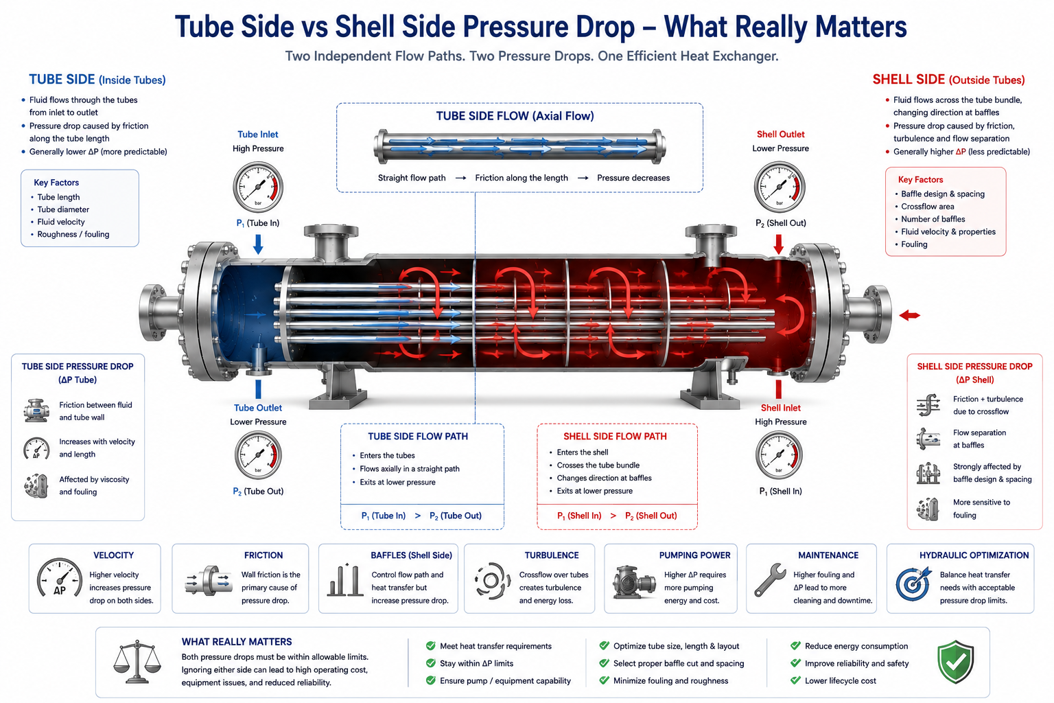
Every shell-and-tube heat exchanger has two separate hydraulic systems—the tube side and the shell side. Although both contribute to the exchanger’s overall performance, they behave very differently, are influenced by different design parameters, and create different operational challenges. Understanding the distinction is essential for designing exchangers that perform efficiently without becoming hydraulic bottlenecks.
When engineers review a heat exchanger’s thermal design report, they often see two pressure drop values:
- Tube-side pressure drop
- Shell-side pressure drop
At first glance, they appear to be similar hydraulic calculations.
In reality, they represent two entirely different flow environments.
The tube side resembles fluid flowing through a network of small pipes with relatively predictable flow paths.
The shell side is much more complex. Fluid changes direction repeatedly as it flows across tubes, around baffles, through bypass gaps, and across window sections. The resulting pressure losses are far more difficult to predict and optimize.
This difference explains why an exchanger may have an acceptable pressure drop on one side while exceeding the allowable limit on the other.
Experienced heat exchanger designers never evaluate these two values together as a single number. They analyse them independently because each side responds differently to changes in velocity, geometry, fouling, and operating conditions.
This article explains the practical differences between tube-side and shell-side pressure drop, what controls each one, and why understanding both is essential for successful hydraulic design.
Table of Contents
Why Pressure Drop Is Evaluated Separately
The tube side and shell side perform different hydraulic functions and therefore require independent evaluation.
A shell-and-tube heat exchanger contains two completely separate flow circuits.
One process fluid flows inside the tubes.
The other flows through the shell around those tubes.
Since these flow paths are physically different, each experiences its own:
- friction losses
- velocity profile
- flow resistance
- hydraulic limitations
For this reason, thermal design software reports:
- tube-side pressure drop
- shell-side pressure drop
separately.
Both values must satisfy the allowable pressure drop specified in the process datasheet.
Meeting one limit does not compensate for exceeding the other.
Tube-Side Pressure Drop Is Easier to Predict
Flow inside tubes behaves much like flow through industrial piping.
The tube side consists of many parallel tubes connected by channel heads and return passes.
The flow path is relatively well defined.
Pressure losses mainly occur because of:
- wall friction inside the tubes
- entrance losses
- exit losses
- return losses in multi-pass exchangers
Because the geometry is straightforward, tube-side hydraulic calculations are generally more predictable than shell-side calculations.
Engineers can usually estimate tube-side pressure drop with reasonable confidence early in the design process.
Shell-Side Pressure Drop Is More Complex
Shell-side flow changes direction repeatedly, creating multiple sources of hydraulic resistance.
Unlike tube-side flow, shell-side fluid does not follow one straight path.
Instead, it flows:
- across the tube bundle
- through baffle windows
- around bypass gaps
- between tube rows
- around sealing strips
- through leakage paths
Each change in direction creates additional hydraulic losses.
Flow separation, recirculation, and local turbulence further complicate the pressure distribution.
This complexity explains why shell-side hydraulic calculations require more sophisticated methods than simple pipe flow equations.
What Primarily Controls Tube-Side Pressure Drop?
Tube-side pressure drop is mainly influenced by flow velocity and tube geometry.
Several factors increase tube-side pressure drop:
- higher fluid velocity
- smaller tube diameter
- longer tube length
- more tube passes
- higher fluid viscosity
Conversely, larger tubes or fewer passes generally reduce hydraulic resistance.
However, these same changes may also reduce heat transfer performance.
Tube-side design therefore involves balancing thermal and hydraulic objectives.
What Primarily Controls Shell-Side Pressure Drop?
Shell-side pressure drop depends heavily on exchanger internals rather than simply the shell diameter.
Important factors include:
- baffle spacing
- baffle cut
- shell diameter
- tube layout
- tube pitch
- sealing strips
- shell-side velocity
Among these, baffle design often has the greatest influence.
Closer baffle spacing usually:
- improves heat transfer
- increases shell-side pressure drop
Wider spacing reduces hydraulic resistance but may also reduce thermal performance.
The next article in this series explores the influence of baffles in much greater detail.
Tube Side Usually Has Higher Velocity
Smaller flow passages naturally create higher velocities.
Since process fluid flows through relatively small tubes, tube-side velocity is often higher than shell-side velocity.
Higher velocity provides:
- better turbulence
- higher heat transfer coefficient
but also produces:
- higher friction
- greater pressure loss
- increased erosion potential
Selecting an appropriate tube velocity is therefore one of the most important hydraulic decisions during exchanger design.
Shell Side Often Determines the Final Design
Although tube-side calculations are simpler, shell-side hydraulics frequently govern exchanger selection.
Many exchanger revisions occur because shell-side pressure drop exceeds the allowable limit.
Unlike the tube side, shell-side modifications often require changing:
- shell diameter
- baffle arrangement
- tube layout
- bundle geometry
These changes affect:
- heat transfer
- fabrication cost
- exchanger size
- maintenance accessibility
As a result, shell-side optimization often becomes the most challenging part of thermal design.
Fouling Affects Both Sides Differently
The location of fouling determines which pressure drop increases most rapidly.
Suppose fouling develops primarily inside the tubes.
The tube-side pressure drop will gradually increase because the effective flow area decreases.
If fouling develops on the shell side instead, restrictions form between the tubes and baffles.
The shell-side pressure drop becomes the dominant concern.
Monitoring which side experiences the greater increase often helps engineers identify where fouling is occurring.
Tube-Side Pressure Drop Is Easier to Troubleshoot
The flow path is more accessible and easier to understand.
When tube-side pressure drop increases unexpectedly, engineers typically investigate:
- tube fouling
- tube plugging
- reduced flow area
- blocked passes
These causes are relatively straightforward.
Shell-side pressure drop is often more difficult to diagnose because flow occurs through many interconnected paths that cannot be observed directly during operation.
Hydraulic Flexibility Differs Between the Two Sides
Some design changes affect one side much more than the other.
If tube-side pressure drop becomes excessive, engineers may consider:
- increasing tube diameter
- reducing tube passes
- shortening tube length
If shell-side pressure drop becomes excessive, possible modifications include:
- increasing shell diameter
- changing baffle spacing
- modifying baffle cut
- improving sealing arrangements
The available design options therefore depend on which side is hydraulically limiting.
Pressure Drop Trends Help Identify Operating Problems
Monitoring each side separately provides valuable diagnostic information.
Operators often trend:
- tube-side differential pressure
- shell-side differential pressure
independently.
Different patterns indicate different problems.
For example:
A gradual increase only on the tube side may indicate internal scaling.
An increase only on the shell side may suggest shell-side fouling or restricted crossflow.
If both increase simultaneously, the exchanger may be experiencing broader process changes or severe fouling.
These trends are valuable for maintenance planning.
Tube Side and Shell Side Do Not Need Equal Pressure Drop
Hydraulic limits depend on the process, not on maintaining equal values.
Some engineers mistakenly assume both sides should have similar pressure losses.
There is no such requirement.
One process stream may tolerate:
- relatively high pressure drop
while the other has:
- very limited allowable pressure loss.
For example:
Cooling water supplied by a dedicated pump may tolerate greater pressure drop than a low-pressure hydrocarbon vapor stream connected to a compressor suction.
Each side is therefore designed according to its own hydraulic limitations.
Common Misunderstandings About Tube-Side and Shell-Side Pressure Drop
Many hydraulic design errors occur because both sides are treated as though they behave the same way.
“Tube-Side and Shell-Side Pressure Drop Should Be Equal”
No.
Each side has independent hydraulic requirements determined by the overall process.
“The Side with Higher Pressure Drop Has the Poorer Design”
Not necessarily.
Higher pressure drop may simply reflect:
- available pump head,
- acceptable operating conditions,
- process priorities.
The important question is whether the pressure drop remains within the allowable limit.
“Shell-Side Pressure Drop Depends Only on Shell Diameter”
Shell diameter is only one factor.
Baffle design, tube layout, leakage streams, and flow distribution often have greater influence.
“Tube-Side Calculations Are Always More Important”
Both sides are equally important.
The limiting side determines the final exchanger design.
Operator Perspective
Operators often identify which side is causing the problem long before the exchanger is opened.
Typical observations include:
- increasing tube-side differential pressure after scaling,
- gradual shell-side pressure increase because of fouling,
- declining process flow,
- increasing pump load,
- unstable process temperatures.
Trending each side independently helps maintenance teams focus on the correct cleaning strategy and reduces unnecessary shutdown work.
Owner Perspective
Understanding both hydraulic systems improves long-term reliability and operating economy.
For plant owners, balancing tube-side and shell-side pressure drop provides:
- lower pumping costs,
- improved thermal performance,
- better maintenance planning,
- longer exchanger service life,
- reduced production interruptions.
A hydraulically balanced exchanger usually delivers lower lifecycle cost than one optimized only for heat transfer.
Final Perspective
Although they are often reported together in thermal design reports, tube-side and shell-side pressure drop represent two very different hydraulic systems.
Tube-side pressure drop is generally easier to calculate, predict, and troubleshoot because the flow path resembles conventional piping.
Shell-side pressure drop is more complex, influenced by baffles, leakage paths, crossflow, and exchanger geometry.
Successful heat exchanger design requires optimizing both systems independently while ensuring that neither exceeds its allowable hydraulic limit.
Only when both sides are properly balanced can the exchanger deliver efficient heat transfer, stable operation, and reliable long-term performance in an industrial process plant.
Explore the complete series in the Heat Exchanger Engineering Hub.

A practicing chemical engineer with 17+ years of experience in process design, project execution, commissioning, and plant operations. Focused on practical engineering judgment beyond textbook explanations.